
TB 9-6625-134-24
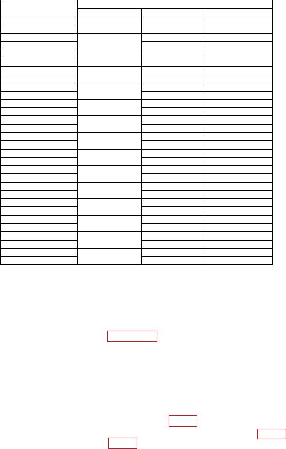
Table 5. Channel B Oscilloscope Readout DCV.
Calibrator output
TI
(V)
Range/div (V)
Minimum (V)
Maximum (V)
6m
4.9 m
7.1 m
2m
-6 m
-7.1 m
-4.9 m
15 m
14.3 m
15.7 m
5m
-15 m
-15.7 m
-14.3 m
30 m
29.1 m
30.9m
10 m
-30 m
-30.9 m
-29.1 m
60 m
58.6 m
61.4 m
20 m
-60 m
-61.4 m
-58.6 m
100 m
98 m
102 m
50 m
-100 m
-102 m
-98 m
300 m
291m
309 m
100 m
-300 m
-309 m
-291 m
600 m
586 m
614 m
200 m
-600 m
-614 m
-586 m
1
980 m
1.020
500 m
-1
-1.020
-980 m
3
2.91
3.09
1
-3
-3.09
-2.91
6
5.86
6.14
2
-6
-6.14
-5.86
10
9.80
10.20
5
-10
-10.20
-9.80
30
29.1
30.9
10
-30
-30.9
-29.1
60
58.6
61.4
20
-60
-61.4
-58.6
100
98.0
102.0
50
-100
-102.0
-98.0
300
291
309
100
-300
-309
-291
(7) Reduce calibrator output to minimum and move connection from INPUT B to
INPUT A and set calibrator output to 0 mV and OPR.
(8) Press TI keys as listed in (a) through (h) below.
(a) SAVE.
(b) F2 RECALL
(c) Select CAL_A saved in paragraph 7 above using the
keys.
(d) ENTER.
(e) A, F4 INPUT A OPTIONS, using
keys select Bandwidth:
20 kHz, ENTER.
(f) CLEAR.
(g) Using mV RANGE V set the Input A sensitivity to 2 mV/div.
(h) Using MOVE move the Input A ground level to the center grid line.
(9) Set calibrator to 6 mV and output to OPR.
(10) If TI A readout is not within limits listed in table 6 perform b below.
(11) Repeat technique of (8)(g), (9) and (10) above for remaining rows in table 6. If TI
A readout is not within limits listed in table 6 perform b below.
9

