
TB 9-6625-1356-35
NOTE
On some instruments, the voltage at A2TP2 may not be within
limits indicated in (10) above. If voltage is not less than -200
mV, and output flatness and distortion specifications are met,
the instrument will be considered acceptable.
(11) Turn FREQUENCY dial to 1.
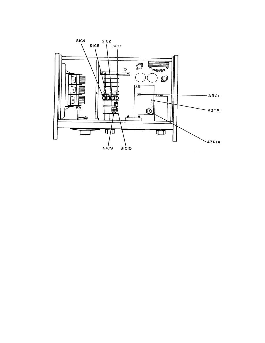
(12) Readjust S1C2 and S1C7 until multimeter indicates -350 mV and frequency
counter indicates 1.00 kHz.
(13) Turn FREQUENCY dial until frequency counter indicates 5.0 kHz.
(14) Remove FREQUENCY dial knob and loosen four dial retaining screws. Slip
FREQUENCY dial until 5 on dial is aligned with reference marker. Tighten retaining
screws and reinstall FREQUENCY dial knob.
(15) Repeat (9) through (14) above until TI is within tolerance in (10) and (12) above.
NOTE
S1C2 and S1C7 are the only adjustments for X10, X100, X1K,
and X10K ranges.
(16) Set FREQUENCY RANGE switch to X1M and turn FREQUENCY dial to 10.
NOTE
During remaining adjustments, remove TI top or bottom cover
to make adjustments. Reinstall covers for measurements.
8

