
TB 9-6625-1493-24
(3) Set calibrator for an initial 200 mV dc output. Using output adjustment control,
adjust calibrator for a +0.2 TI meter indication. Calibrator Error display will indicate
<15 percent; if not perform, b below.
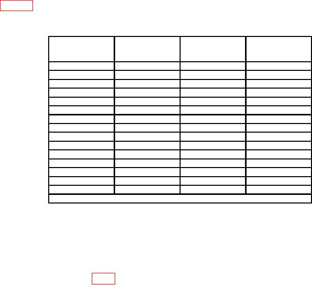
(4) Adjust calibrator for the initial output, then TI meter indication, as listed in
table 3. If calibrator Error indication is not within specified limits, and b was not
performed in (3) above, perform b below.
Table 3. Conventional Voltmeter Accuracy
Test instrument
Calibrator
RANGE
Error indications
Calibrator
Test instrument
(%)
switch settings
initial outputs
meter indications
1
0.4 V
+0.4
7.5
1
0.6 V
+0.6
5.0
1
0.8 V
+0.8
3.75
1
1.0 V
+1
3.0
1
1
1.0 V
-1
3.0
1
0.8 V
-0.8
3.75
1
0.6 V
-0.6
5.0
1
0.4 V
-0.4
7.5
1
200
mV
-0.2
15.0
10
10
V
-1
3.0
2
10
10
V
+1
3.0
100
100
V
+1
3.0
1001
100
V
-1
3.0
1000
1000
V
-1
3.0
10002
1000
V
+1
3.0
REDUCE CALIBRATOR OUTPUT TO A MINIMUM
1Set
FUNCTION switch to - (negative).
2Set
FUNCTION switch to + (positive).
b. Adjustments
(1) If necessary, set TI function switch to + (positive) and set calibrator for a +1.0 V
dc output.
(2) Adjust R230 (fig. 1) for a TI indication of +1 (R).
9. Differential Voltmeter Dc Voltage Accuracy (Transfer Level)
a. Performance Check
(1) Short INPUT to COMMON terminal.
(2) Position controls as listed in (a) through (c) below:
(a) RANGE switch to 1.
(b) Voltage dials to 000000.
(c) NULL switch to .0001.
(3) Adjust ZERO control for indication on meter.
(4) Set NULL switch to TVM, then remove short from INPUT and COMMON terminals.
(5) Connect calibrator output to TI INPUT, COMMON, and ground terminals.

