
TB 9-6625-1493-35
b. Adjustments
(1) If necessary, set TI function switch to + (positive) and set calibrator for a +1.0 V
dc output.
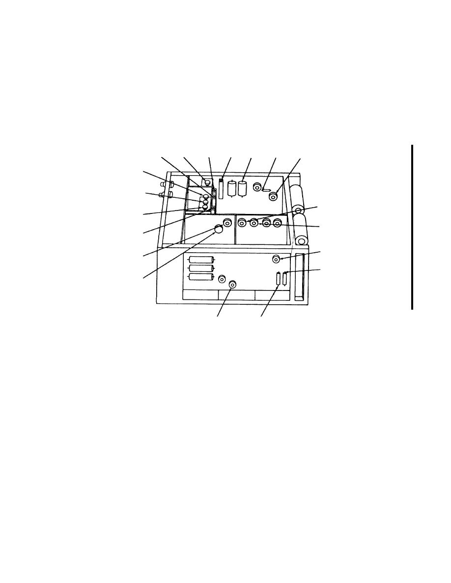
(2) Adjust R230 (fig. 1) for a TI indication of +1 (R).
C5021
R503
R538(+)
R539
R403
C518(-)
R406
C4011
C4031
R120
C4051
R111
R410
R230
R122
C219(+)
R103
C215(-)
R231
1
REMOVE CAP FROM CAPACITOR TO GAIN ACCESS TO ADJUSTMENT.
Figure 1. Differential Voltmeter -adjustment locations.
a. Performance Check
(1) Short INPUT to COMMON terminal.
(2) Position controls as listed in (a) through (c) below:
(a) RANGE switch to 1.
(b) Voltage dials to 000000.
(c) NULL switch to .0001.
(3) Adjust ZERO control for indication on meter.
(4) Set NULL switch to TVM, then remove short from INPUT and COMMON
terminals.
(5) Connect calibrator output to TI INPUT, COMMON, and ground terminals.
CHANGE 1

