
TB 9-6625-151-40
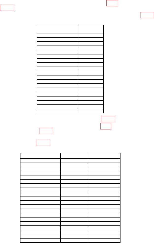
(2) Measure resistance between connector TI J2 pin Z (fig. 1) and first test point
listed in table 4. MULTIMETER will indicate as listed.
(3) Repeat technique of (2) above for TI J2-Z and remaining J2 test points in table 4.
Table 4. Continuity J2-Z to J2-x.
Test Point
J2 Pin -
indication
A
OPEN
B
OPEN
C
OPEN
D
OPEN
E
OPEN
F
OPEN
G
OPEN
H
OPEN
J
OPEN
K
OPEN
L
OPEN
M
OPEN
N
OPEN
P
OPEN
R
OPEN
S
OPEN
T
OPEN
U
OPEN
V
OPEN
(4) Set TI SW1 Tube Select switch to first position in table 5.
(5) Connect a test lead to TI fuze module M439 CHG (fig. 1) and measure resistance
to first J2 test point listed in table 5. MULTIMETER will indicate as listed.
(6) Repeat technique of (4) and (5) above for remaining SW1 Tube Select settings,
J2 test points and limits in table 5.
Table 5. Continuity M439 Charge to J2-x, Tube Select.
Tube select
Test point
Max Ω
SW1
J2-pin -
1
A
0.5
2
B
0.5
3
C
0.5
4
D
0.5
5
E
0.5
6
F
0.5
7
G
0.5
8
H
0.5
9
J
0.5
10
K
0.5
11
L
0.5
12
M
0.5
13
N
0.5
14
P
0.5
15
R
0.5
16
S
0.5
17
T
0.5
18
U
0.5
19
V
0.5
5

