
TB 9-6625-160-24
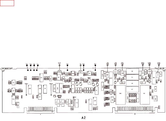
(5) Set CALIBRATOR frequency to 40 kHz. Adjust A2C3 (HIGH 12 DB) as shown in
figure 2 below, for a reading on right display between 99.70 and 100.3%.
(6) Set CALIBRATOR frequency to 100 kHz. Adjust A2C3 for a reading between
99.50 and 100.5%. Repeat technique of (5) and (6) as often as needed until flatness at
40 kHz and 100 kHz is within limits specified. (See the following note.)
NOTE
If the flatness cannot be adjusted so that the 40 kHz and
100 kHz readings are both within the given limits, change
A2C4 as follows: If the 100 kHz reading is higher than at
40 kHz, decrease A2C4 by approximately 10%. If the 40 kHz
reading is higher than that at 100 kHz, increase A2C4 by
approximately 10%.
Figure 2. Flatness Adjustment Locations.
(7) On TI, press RATIO to turn it off. Key in 1.7 SPCL to set input to 18.9 V range.
(8) Set CALIBRATOR frequency to 1 kHz and level to 15 V rms.
(9) TI right display should read between 14.7 and 15.3 V. Press RATIO.
(10) Set CALIBRATOR frequency to 40 kHz. Adjust A2C10 (HIGH 24 DB) for a
reading on right display between 99.70 and 100.3%.
(11) Set CALIBRATOR frequency to 100 kHz. Adjust A2C10 for a reading between
99.50 and 100.5%. Repeat technique of (10) and (11) as often as needed until flatness at
40 kHz and 100 kHz is within limits specified.
NOTE
If the flatness cannot be adjusted so that the 40 kHz and
100 kHz readings are both within the given limits, change
A2C9 as follows: If the 100 kHz reading is higher than at
40 kHz, decrease A2C9 by approximately 10%. If the 40 kHz
reading is higher than that at 100 kHz, increase A2C4 by
approximately 10%.
(12) On TI, press RATIO to turn it off. Key in 1.4 SPCL to set input to 75.4 V range.
(13) Set CALIBRATOR frequency to 1 kHz and level to 60 V rms.
(14) TI right display should read between 58.8 and 61.2 V. Press RATIO.
19

