
TB 9-6625-168-24
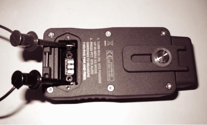
Figure 2. TI Battery Contact Location And Power Supply Connection.
d. Configure multimeter for DC Volts measurement and set DC power supply output
for a 5.5 V dc multimeter indication.
e. Configure multimeter for DC current measurements and measure DC current with
TI turned off. Multimeter A dc indication should be <200 nA dc.
f. Set TI to On (in Receiver Test mode) and measure DC current. Multimeter A dc
indication should be <8 mA dc.
g. Connect RF power amplifier output, through RF power meter sensor, to TI RADIO input.
h. Ensure RF power amplifier output level control is set to minimum.
i. Set signal generator for an output of 75 MHz @ 0 dBm.
j.
Slowly increase RF power amplifier for an RF power meter indication of 2 W.
k. With TI in Transmitter Test mode, measure DC current. Multimeter A dc indication
should be <15 mA dc.
l.
Set all outputs to minimum and keep equipment connected.

