
TB 9-6625-1914-24
center graticule line 1 division, perform b (9) below.
(8) Adjust FREQUENCY control to positions listed in table 7 and adjust signal
generator frequency to align signal pip with right graticule line on display. If signal
corresponding control position, using technique listed in b (10) through (14) below.
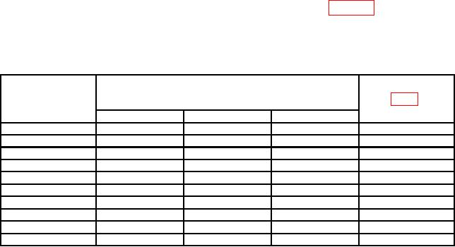
Table 7. Tuning Dial Accuracy
Signal generator
Test instrument
Adjustments
indications
FREQUENCY
(MHz)
control positions
(R)
(MHz)
Min
Nominal
Max
15
19
20
21
A5A1R38
25
29
30
31
A5A1R41
35
39
40
41
A5A1R44
45
49
50
51
A5A1R47
55
59
60
61
A5A1R50
65
69
70
71
A5AlR53
75
79
80
81
A5A1R56
85
89
90
91
A5A1R59
95
99
100
101
A5A1R62
105
109
110
111
A5A1R65
(9) Position TI controls as listed in (a) through (d) below:
(a) SCAN WIDTH (red) switch to 0-100 MHz.
(b) FREQUENCY control to 50 MHz.
(c) BANDWIDTH switch to 300 kHz.
(d) SCAN WIDTH PER DIVISION switch to 1 MHz.
(10) Adjust signal generator frequency to 50 MHz. If signal pip does not align with
center graticule line +0.40 division on display, perform b (15) below.
NOTE
Steps (11) through (13) below are applicable only to model
8553B.
(11) Position TI controls as listed in (a) through (d) below:
(a) SCAN WIDTH (red) switch to PER DIVISION.
(b) BANDWIDTH switch to 30 kHz.
(c) RANGE MHz switch to 0-11.
23

