
TB 9-6625-1918-24
EQUIPMENT REQUIREMENTS
calibration procedure. This equipment is issued with Secondary Transfer Calibration
Standards Set AN/GSM-287 or AN/GSM-705.
Alternate items may be used by the
calibrating activity. The items selected must be verified to perform satisfactorily prior to
use and must bear evidence of current calibration. The equipment must meet or exceed the
to-one ratio between the standard and TI. Where the four-to-one ratio cannot be met, the
actual accuracy of the equipment selected is shown in parenthesis.
5. Accessories Required. The accessories required for this calibration are common
usage accessories, issued as indicated in paragraph 4 above, and are not listed in this
calibration procedure.
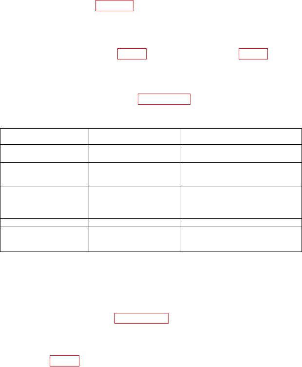
Table 2. Minimum Specifications of Equipment Required
Common name
Minimum use
Manufacturer and model
specifications
(part number)
AUTOTRANSFORMER
Range: 105 to 125 V ac
Ridge, Model 9020A
(9020A)
Range: 0 to 255 V dc
Fluke, Model 8840A/AF05
0 to 3 V ac
(AN/GSM-64D)
Accuracy: 1%
POWER METER
Range: 0 to 10 mW
Agilent, Model E12-432A (MIS-
Accuracy: 6%
30525) w/thermistor mount, Agilent,
Model 478A-H75 (7915907) or 8478B
(8478B)
POWER SPLITTER
Range: DC to 18 GHz
Weinschel, Model 1870A (7916839)
SYNTHESIZED SIGNAL
Range: 10 MHz to 10 GHz
Anritsu, Model 68369NV (68369NV)
CALIBRATION PROCESS
6. Preliminary Instructions
a. The instructions outlined in paragraphs 6 and 7 are preparatory to the calibration
process. Personnel should become familiar with the entire bulletin before beginning the
calibration.
b. Items of equipment used in this procedure are referenced within the text by common
name and listed in table 2.
c. Unless otherwise specified, verify the result of each test and, whenever the test
requirement is not met, take corrective action before continuing with the calibration.
Adjustments required to calibrate the TI are included in this procedure.

