
TB 9-6625-1935-24
11. Zero Carryover Test
a. Performance Check
(1) Deenergize and disconnect TI to power meter calibrator and multimeter.
Connect thermistor mount to TI.
(2) If applicable, set OPERATE/CALIBRATE SWITCH A2S1 (fig. 1) to OPERATE.
(3) Energize TI and allow 10 minutes to warm-up and stabilize.
(4) Set RANGE switch to COARSE ZERO and adjust COARSE ZERO
screwdriver adjustment for a 0 indication on TI meter.
(5) Set RANGE switch to .01 mW (10 μW on model 432B).
(6) Press FINE ZERO switch.
If TI meter does not indicate 0 0.05 μW,
perform b below.
(7) Set RANGE switch to each position (except AUTO on model 432B). If TI meter
does not indicate within one-fourth minor division of 0 for model 432A, or does not indicate
within specified limits in table 5 for model 432B, perform b below.
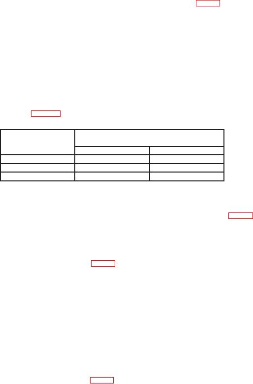
Table 5. Zero Carryover Test
RANGE
switch
Meter indications
settings
Min
Max
100 μW
-0.5
μW
+0.5
μW
1 mW
-0.005 mW
+0.005 mW
10 mW
-0.05 mW
+0.05 mW
b. Adjustments
(1) Press FINE ZERO switch and adjust A1R43 AUTO ZERO ADJ (fig. 3) for a 0
indication. For model 432B, if TI meter cannot be adjusted to 0, perform (2) through (8)
below (R).
NOTE
A1R43 AUTO ZERO ADJ (fig. 3) is not included on some 432A
models.
(2) Deenergize TI and remove front meter cover and side panels. Remove circuit
board assemblies A1 and A2.
(3) Reinstall meter with readout device exposed.
CAUTION
Assure meter is installed right-side-up and that connectors
XM1 and XM2 are not reversed or shorted. If power is applied
while meter is installed upside-down, meter will be damaged.
(4) Short pins 10 and 12 of XA2 (fig. 4) together.

