
TB 9-6625-1942-24
(5) Set TI RANGE switch to 10 V and set calibrator output amplitude to 10 V ac. If
TI indication is not between 9.9870 and 10.0130 V ac, perform b (3) below.
(6) Set calibrator output to 10 V ac at 50 kHz. If TI indication is not between 9.9870
and 10.0130 V ac, perform b (4) below.
(7) Set TI RANGE switch to 100V and set calibrator output amplitude to 100 V ac
at 100 Hz. If TI indication is not between 99.870 and 100.130 V ac, perform b (5) below.
(8) Set calibrator output to 100 V ac at 50 kHz. If TI indication is not between
99.870 and 100.130 V ac, perform b (6) below.
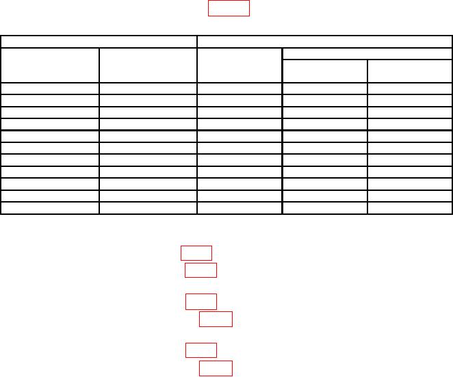
(9) Repeat technique of (7) and (8) above for calibrator frequencies and RANGE
switch settings and indications as listed in table 4.
Table 4. Ac Volts Accuracy
Calibrator
Test instrument
RANGE
Output
Indications
Output
voltage
switch settings
(V ac)
(V ac)
Min
Max
20 Hz
1.0
1
0.99540
1.00460
10 kHz
1.0
1
0.99870
1.00130
10 kHz
10.0
10
09.9870
10.0130
20 Hz
10.0
10
09.9540
10.0460
20 Hz
100.0
100
099.540
100.460
10 kHz
100.0
100
099.870
100.130
10 kHz
500.0
1000
0499.20
0500.80
100 Hz
500.0
1000
0499.20
0500.80
20 Hz
500.0
1000
0497.40
0502.60
250 kHz
1.0
1
0.99180
1.00820
250 kHz
10.0
10
9.918
10.082
b. Adjustments
(1) Adjust A6R32 1V HF ADJ (fig. 1) for 1.00000 indication on TI (R).
(2) Adjust A6R27 1V LF ADJ (fig. 1) for 1.00000 indication on TI. Repeat a (3) and
(4) above until indications are correct (R).
(3) Adjust A6R28 10V LF ADJ (fig. 1) for 10.0000 indication on TI (R).
(4) Adjust A6C27 10V HF ADJ (fig. 1) for 10.0000 indication on TI. Repeat a (5)
and (6) above until indications are correct (R).
(5) Adjust A6R3 100V LF ADJ (fig. 1) for 100.000 indication on TI (R).
(6) Adjust A6C6 100V HF ADJ (fig. 1) for 100.000 indication on TI. Repeat a (7)
and (8) above until indications are correct (R).
10. Dc/dc Ratio (Option 080 Only)
a. Performance Check
(1) Position controls as listed in (a) through (c) below:

