
TB 9-6625-1947-24
(14) Set FREQUENCY dial to 5. If frequency counter does not indicate between
4.935 MHz and 5.065 MHz, go to (15) below. If (15) below is not performed, proceed to (16)
below.
(15) Set FREQUENCY DIAL to 10. If frequency counter indication was high, adjust
counter reading and repeat (12) through (14) above (R).
and 1013 kHz and multimeter reading at A2TP2 (fig. 1) between -0.3 V and -0.4 V (R).
(17) Repeat (1) through (16) above until frequencies are within specified limits.
9. Meter Tracking and Output Voltage Flatness
a. Performance Check
(1) Connect multimeter to TI UNBAL output using 50
feed-through termination.
(2) Position controls as listed in (a) through (c) below:
(a) FREQUENCY RANGE switch to X1K.
(b) FREQUENCY dial to 1.
(c) OUTPUT LEVEL dBm switch to +10.
(3) Adjust AMPLITUDE control for a 0 dBm indication on TI meter. If multimeter
does not indicate between 0.7000 V rms and 0.7142 V rms, perform b below. Record indication
as R1.
(4) Adjust AMPLITUDE control for a 1.0 dBm indication on TI meter. Divide
multimeter indications by R1 value recorded in (3) above. If quotient is not between 1.111
and 1.133, perform b (1) through (10) below.
(5) Repeat technique of (4) above, using TI meter indications listed in table 4. If
quotients are not within limits specified, perform b (1) through (10) below.
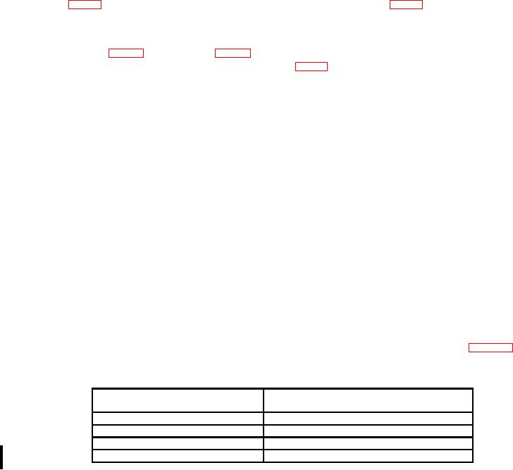
Table 4. Meter Tracking
Test instrument meter indications
Multimeter indications
(dBm)
(V Ac)
+0.8
V ac R1 = 1.085 to 1.107
+0.4
V ac R1 = 1.037 to 1.058
-0.4
V ac R1 = .945 to .965
-0.8
V ac R1 = .900 to .921
(6) Adjust AMPLITUDE control to minimum and disconnect multimeter and
termination from TI.
(7) Connect thermal converter to UNBAL output.
(8) Connect multimeter to thermal converter.
(9) Adjust AMPLITUDE control for a 0 dBm indication on TI meter and record dc
voltage indication on multimeter as R2.

