
TB 9-6625-1957-35
(3) Rotate calibrator knob below EDIT FIELD pushbutton to adjust calibrator
display indication to equal TI indication. If calibrator err display does not indicate within
limits specified in first row of table 6, perform b below.
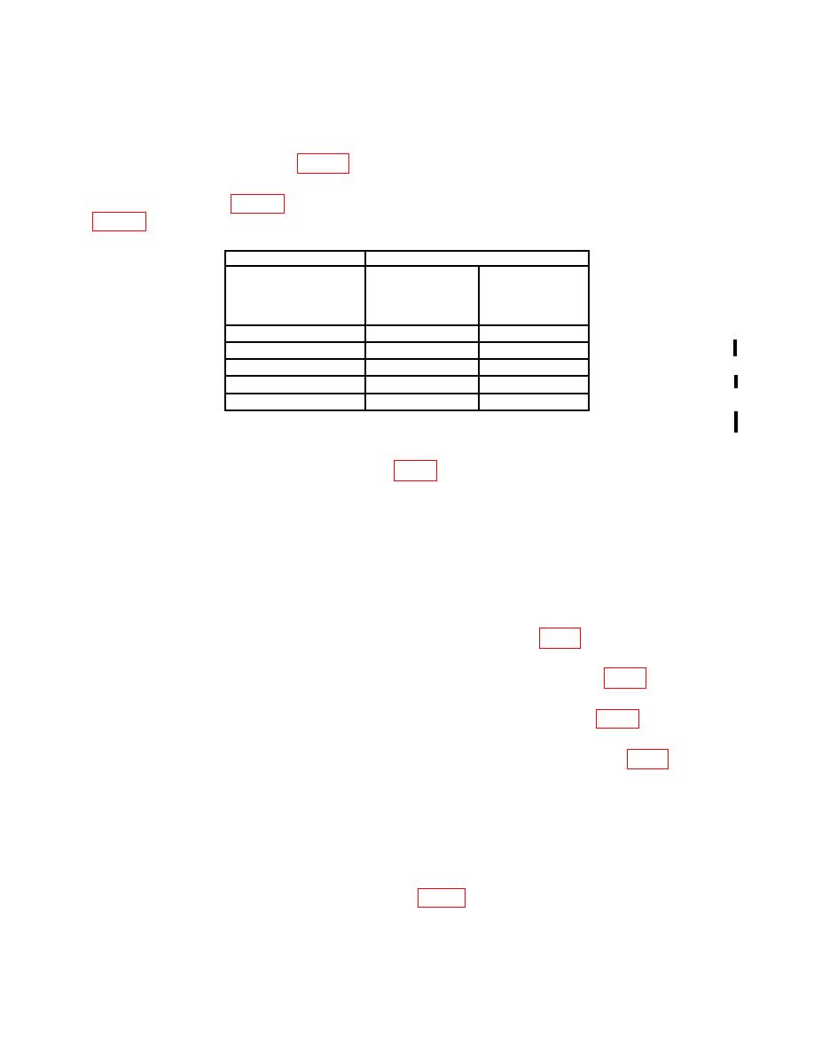
(4) Repeat technique of (1) through (3) above, using calibrator outputs and TI
indications listed in table 6. Calibrator err display will indicate within limits specified in
Table 6. Resistance
Test instrument
Calibrator
err
RANGE/FUNCTION
display
Nominal
settings
indication
output
(%)
.31
kΩ
kΩ
200
190
21
.31
kΩ
kΩ
1.9
.31
kΩ
kΩ
20
19
22
.31
MΩ
MΩ
1.9
.51
MΩ
MΩ
20
19
Set calibrator 2 WIRE COMP to on.
1
Set calibrator 2 WIRE COMP to off.
2
displayed value for 190 kΩ (R).
12. Power Supply
a. Performance Check
NOTE
Do not perform power supply check if all other parameters are
within tolerance.
(1) Connect digital multimeter between TP 1 PIN 24 +5V (fig. 1) and chassis
ground. If digital multimeter does not indicate between 4.9 and 5.1 V dc, perform b below.
(2) Connect digital multimeter positive lead to TP 2 VR 410 +12 V (fig. 1). Digital
multimeter will indicate between 11.0 and 13.0. V dc.
(3) Connect digital multimeter positive lead to TP 3 PIN 15 -12 V (fig. 1). Digital
multimeter will indicate between -11.4 and -12.6 V dc.
(4) Connect digital multimeter positive lead to TP 6 +12 V FLOATING (fig. 1) and
negative lead to TP 5 FLOATING GROUND. Digital multimeter will indicate between
+11.4 and +12.6 V dc.
(5) Move digital multimeter positive lead to TP4 -12 V FLOATING. Digital
multimeter will indicate between -11.4 and -12.6 V dc.
(6) Move digital multimeter positive lead to TP 7 +5 V FLOATING. Digital
multimeter will indicate between +4.5 and +5.5 V dc.
+5.00 V dc (R).
CHANGE 3

