
TB 9-6625-1959-24
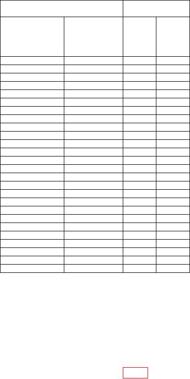
Table 6. Flatness - Continued
Measuring receiver
Test instrument
indication
RANGE
(MHz)
VARIABLE
switch
control
settings
settings
Min
Max
10-25
25
98.5%
101.5%
22.5
98.5%
101.5%
20
98.5%
101.5%
17.5
98.5%
101.5%
15
98.5%
101.5%
12.5
98.5%
101.5%
10
98.5%
101.5%
25-50
25
98.5%
101.5%
30
98.5%
101.5%
35
98.5%
101.5%
40
98.5%
101.5%
45
98.5%
101.5%
50
98.5%
101.5%
50-100
100
98.5%
101.5%
90
98.5%
101.5%
80
98.5%
101.5%
70
98.5%
101.5%
60
98.5%
101.5%
50
98.5%
101.5%
100-250
100
97%
103%
125
97%
103%
150
97%
103%
175
97%
103%
200
97%
103%
225
97%
103%
250
97%
103%
b. Adjustments. No adjustments can be made.
12. Power Supply
NOTE
Do not perform power supply check if all other parameters are
within tolerance.
a. Performance Check
(1) Connect multimeter HI to-22 VOLT TP (fig. 2) and LO to chassis ground. If
multimeter does not indicate between -21.95 and -22.05 V dc, perform b below.

