
TB 9-6625-1963-24
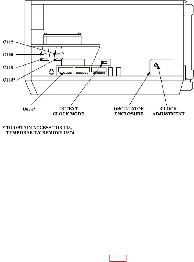
Figure 1. Right side view-component locations.
NOTE
Some oscillators have a metal cover screw which will change
the oscillator frequency when replaced. Verify that frequency
counter indicates proper CLOCK frequency with cover screw in
place.
(5) Allow 4 hours for oscillator stabilization. After 4 hours, oscillator frequency will
not have drifted more than 0.6 Hz (hertz).
b. Adjustments. No further adjustments can be made.
9. Trigger Amplifier Compensation
a. Performance Check
(1) Connect function generator to TI A input.
(2) Set TI A and B COUPL AC switches to DC (out).
(3) Adjust vertical sensitivity of oscilloscope for 20 mV (millivolts) per division.
(4) Connect oscilloscope to test point TP141 (fig. 2), using a X10 probe.

