
TB 9-6625-1966-35
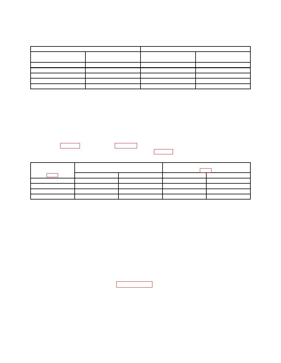
Table 5. Sine Wave Response Continued
Test instrument
Multimeter indications (V Ac)
RANGE
Min
Max
switch settings
dial settings
X1K
5
4.95
5.05
X1K
10
4.95
5.05
X10K
1
4.85
5.15
X10K
5
4.85
5.15
X10K
10
4.85
5.15
b. Adjustments. No adjustments can be made.
15. Power Supply
NOTE
Do not perform power supply check if all other parameters are
within tolerance.
specified, perform appropriate adjustments listed in table 6.
Test instrument
Multimeter
Adjustments
test points
indications (V dc)
Min
Max
Adjustments
Indications
A12C2 (A2C2)
-26.48
-26.52
A12R20 (A2R20)
-26.5
A12C1 (A2C1)
+26.48
+26.52
A12R7 (A2R7)
+26.5
A12C4 (A2C4)
-19.99
-20.01
A12R26 (R3)
-20.0
A12C3 (A2C3)
+19.99
+20.01
A12R25 (R2)
+20.0
1All
power supply adjustments interact; readjust as necessary for best compromise.
b. Adjustments. No further adjustments can be made.
16. Final Procedure
a. Deenergize and disconnect all equipment and reinstall protective cover on TI.
b. Annotate and affix DA label/form in accordance with TB 750-25.
CALIBRATION PROCESS FOR MODEL 3302A
17. Preliminary Instructions
process. Personnel should become familiar with the entire bulletin before beginning the

