
TB 9-6625-1967-35
(7) Repeat (5) above while observing beginning and ending indications of +4 V or
more and -0.5 V or less respectively.
(8) Move multimeter connections to TI Y terminals.
(9) Adjust ZERO REF SET control fully cw.
(10) Lift and hold RECORD/CAMERA switch to RECORD and adjust POSITION
control for a 0.0 V indication on multimeter.
(11) Adjust ZERO REF SET slowly ccw. If multimeter does not rise to
approximately +0.4 V, perform b below. Release RECORD/CAMERA switch.
(12) Move multimeter connections to TI X terminals and lift RECORD/CAMERA
switch to RECORD. Multimeter will indicate between 0 and 1 V as dot moves across crt
screen. Release RECORD/CAMERA switch.
b. Adjustments. Lift RECORD/CAMERA switch to RECORD while adjusting
R7225 (fig. 4) for a +0.4 V indication on multimeter (R).
14. Power Supply
a. Performance Check
NOTE
Do not perform power supply check if all other parameters are
within tolerance.
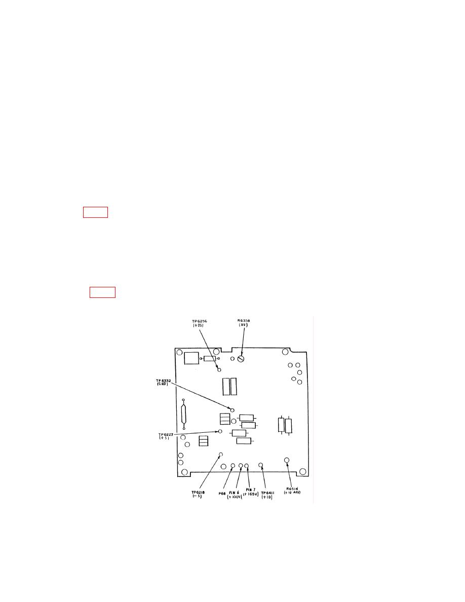
(1) Connect multimeter common lead to TP6332 (GND) and positive lead to TP6256
(+25 V) (fig. 5). If multimeter does not indicate between 24.75 and 25.25 V dc, perform b
below.

