
TB 9-6625-1967-35
(j) VAR screwdriver adjustment fully cw.
(2) Connect termination to TI CABLE connector.
(3) Position trace
on
crt
horizontal
graticule
centerline,
using
POSITION/FINE controls.
(4) Remove termination. If trace shifts by more than 0.5 divisions, perform b below.
(5) Set mρ/DIV switch to 500 or lower to obtain 1.000 V in next step.
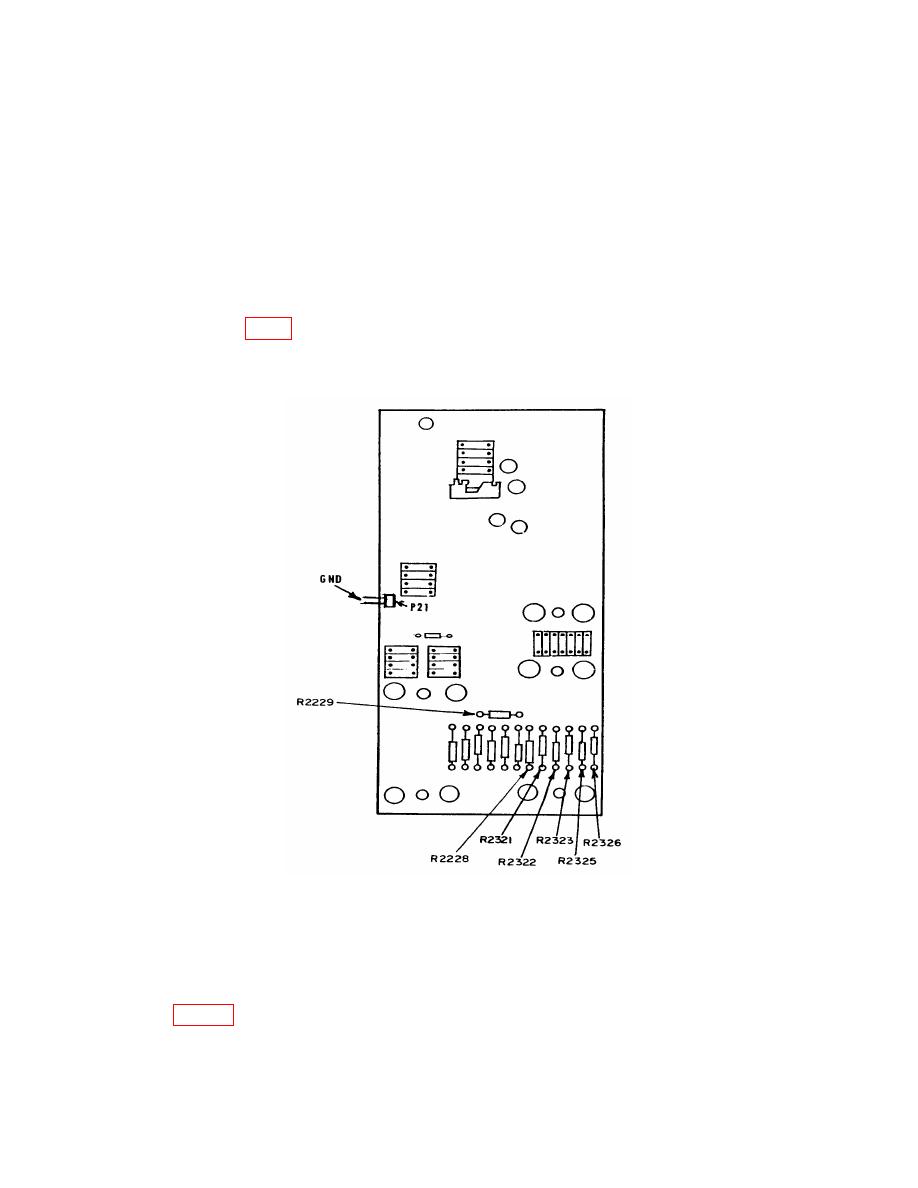
(6) Connect multimeter negative lead to ground terminal of P21 and positive lead to
(7) Adjust POSITION/FINE and ZERO REF (SET) controls until multimeter
indicates 1.000 V 0.008 V.
NOTE
If unable to obtain 1.000 V in (7) above, set mρ/DIV switch to 200.
(8) Repeat technique of (7) above, using only the positive lead to connect to resistors
listed in table 5. Multimeter will indicate within limits specified.
14

