
TB-9-6625-1968-24
(11) Set MODULATION RANGE Hz switch to 100 and adjust MODULATION
RANGE Hz VERNIER control for a 20 Hz indication on audio analyzer.
(12) Set audio analyzer to measure distortion. If audio analyzer does not indicate <2
percent, perform 9 b (3) through (5) below.
(13) Set audio analyzer to measure frequency.
(14) Set MODULATION RANGE Hz switch to 10k, adjust MODULATION
RANGE Hz VERNIER control for a 1 kHz indication on audio analyzer, and repeat (12) above.
(15) Set audio analyzer to measure frequency.
(16) Adjust MODULATION RANGE Hz VERNIER control for a 10 kHz indication
on audio analyzer, and repeat (12) above.
b. Adjustments
(2) Repeat (1) above at frequencies of 1, 10, and 50 kHz.
2 percent (R).
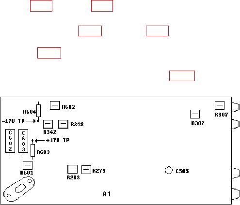
(4) Adjust R307 (fig. 2) for an audio analyzer indication <2 percent (R).
(5) Set MODULATION RANGE Hz switch to 10k and adjust MODULATION
RANGE Hz VERNIER control fully ccw. Adjust R302 (fig. 2) for an audio analyzer
indication <2 percent (R).
Figure 2. Test equipment - top view.
10. Square Wave Rise and Falltime
a. Performance Check
(1) Connect TI Vp-p to oscilloscope Vertical 1 input using 50
feedthrough
termination.

