
TB-9-6625-1968-35
(11) Set MODULATION RANGE Hz switch to 100 and adjust MODULATION
RANGE Hz VERNIER control for a 20 Hz indication on audio analyzer.
(12) Set audio analyzer to measure distortion. If audio analyzer does not indicate <2
percent, perform b (3) through (5) below.
(13) Set audio analyzer to measure frequency.
(14) Set MODULATION RANGE Hz switch to 10k, adjust MODULATION
RANGE Hz VERNIER control for a 1 kHz indication on audio analyzer, and repeat (12) above.
(15) Set audio analyzer to measure frequency.
(16) Adjust MODULATION RANGE Hz VERNIER control for a 10 kHz indication
on audio analyzer, and repeat (12) above.
b. Adjustments
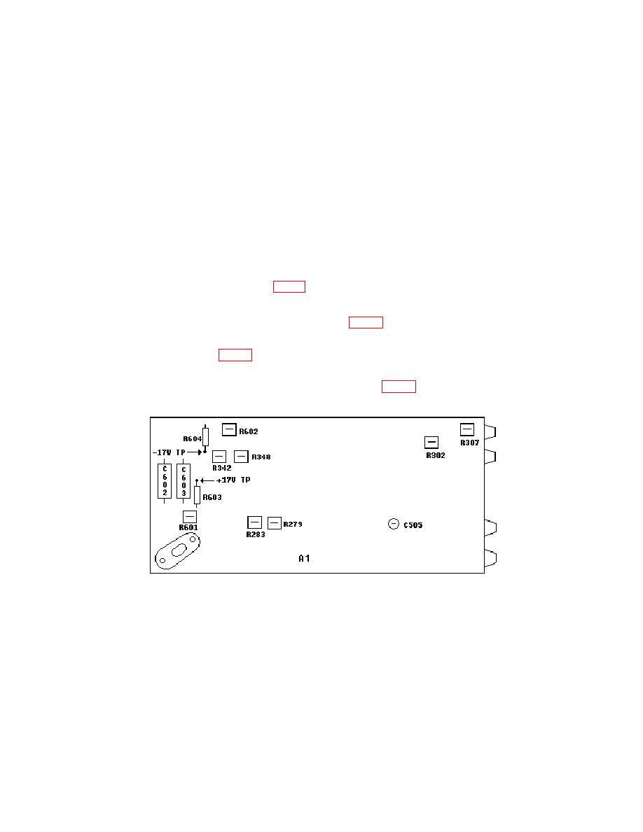
(1) Adjust A1R283 and A1R279 (fig. 2) for an audio analyzer indication <0.5 percent (R).
(2) Repeat (1) above at frequencies of 1, 10, and 50 kHz.
(3) Alternately adjust A1R342 and A1R348 (fig. 2) for an audio analyzer indication
<2 percent (R).
(4) Adjust A1R307 (fig. 2) for an audio analyzer indication <2 percent (R).
(5) Set MODULATION RANGE Hz switch to 10k and adjust MODULATION
indication <2 percent (R).
a. Performance Check
(1) Connect TI Vp-p to oscilloscope Vertical 1 input using 50 Ω feedthrough
termination.

