
TB 9-6625-1998-24
b. Adjustments
(1) Set ATTENUATOR switch to X10 V and OUTPUT CONTROL fully cw.
NOTE
For AN/URM-127, perform (2) through (4) below.
For
AN/URM-127A, perform (5) through (7) below.
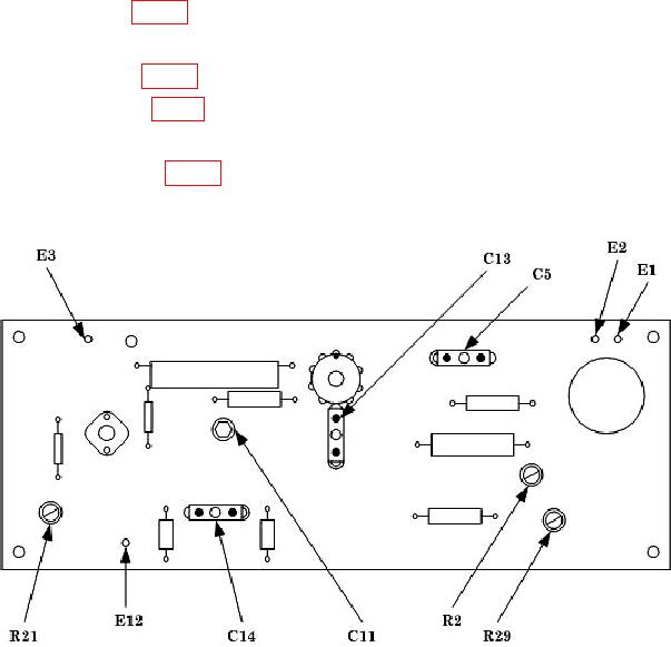
(2) Adjust R2 (fig. 2) until OUTPUT RMS meter indicates 1.15 (R).
(3) Adjust OUTPUT CONTROL until audio analyzer indicates 10 V.
(4) Adjust R29 (fig. 2) until OUTPUT RMS meter indicates 1.0 (R).
(5) Adjust A2R5 (fig. 3) until audio analyzer indicates 12.0 V ac (R).
(6) Adjust OUTPUT CONTROL until audio analyzer indicates 10.0 V ac.
(7) Adjust A2R12 (fig. 3) until VOLTS RMS meter indicates 1.0 (R).
Figure 2. AN/URM-127 - adjustments
6

