
TB 9-6625-1998-24
b. Adjustments. No adjustments can be made.
11. Distortion
a. Performance Check
(1) Connect OUTPUT to audio analyzer INPUT high.
(2) Set ATTENUATOR switch to X10V and OUTPUT CONTROL for 1.0 on
OUTPUT RMS (VOLTS RMS) meter.
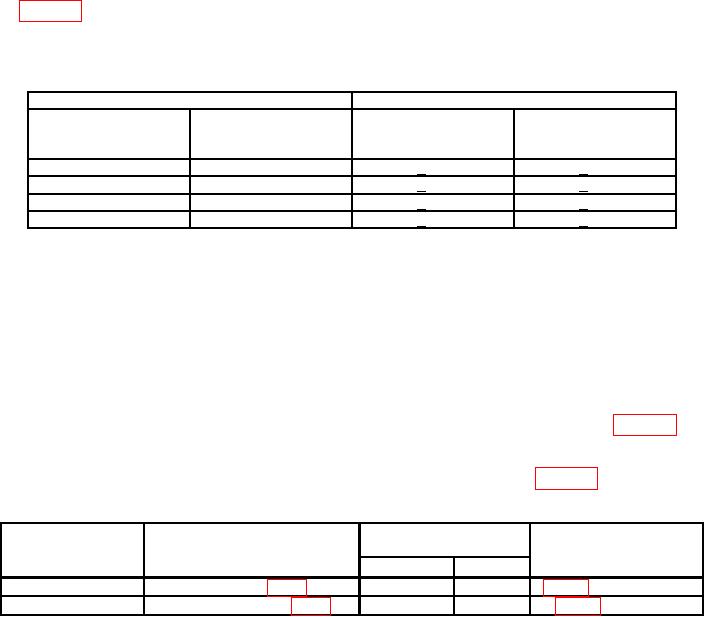
(3) Set FREQ RANGE MULTIPLIER switch and frequency dial to positions listed
in table 5 and measure distortion at each frequency. Audio analyzer will indicate within
limits specified.
Table 5. Distortion
Test instrument
Audio analyzer indications
FREQ RANGE
MULTIPLIER
FREQUENCY dial
switch settings
settings
AN/URM-127
AN/URM-127A
X1
20
< 1%
< 2%
X10
100
< 1%
< 2%
X100
200
< 1%
< 2%
X1K
100
< 1%
< 2%
b. Adjustments. No adjustments can be made.
12. Power Supply
NOTE
Do not perform power supply check if all other parameters are
within tolerance.
a. Performance Check. Connect multimeter between test points listed in table 6. If
multimeter does not indicate within limits specified, perform b below.
b. Adjustments. Perform corresponding adjustments as listed in table 6.
Table 6. Power Supply
Multimeter indications
Adjustments
(V dc)
(R)
Min
Max
Test points
Model
AN/URM-127
E3 and El2 (fig. 2)
46
48
R21 (fig. 2) for 47 V
AN/URM-127A
A4TP5 and A4TP6 (fig. 3)
48
52
A4R4 (fig. 3) for 50 V
13. Final Procedure
a. Deenergize and disconnect all equipment.
b. Annotate and affix DA label/form in accordance with TB 750-25.

