
TB 9-6625-1999-35
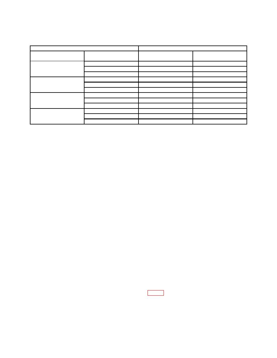
Table 3. Frequency Dial Accuracy - Continued
Test instrument
Frequency counter indications
FREQUENCY dial
Min
Max
RANGE switch settings
settings
530KC - 180KC
530
524.7 kHz
535.3 kHz
1200
118.0 kHz
1212.0 kHz
1800
1782.0 kHz
1818.0 kHz
1.76MC-6.0MC
6.0
5.940 MHz
6.060 MHz
4.0
3.960 MHz
4.040 MHz
1.76
1.7424 MHz
1.776 MHz
5.8MC - 19.2MC
5.8
5.742 MHz
5.858 MHz
12
11.880 MHz
12.120 MHz
19.2
19.008 MHz
19.392 MHz
19MC - 65MC
65
64.350 MHz
65.650 MHz
40
39.6 MHz
40.40 MHz
19
18.810 MHz
19.190 MHz
b. Adjustments. No adjustments can be made.
11. Carrier Zero Set
a. Performance Check
(1) Connect oscilloscope to RF OUTPUT 50 Ω, using termination.
(2) Position controls as listed in (a) through (e) below:
(a) RANGE switch to 50-170KC.
(b) ATTENUATOR VERNIER control fully ccw.
(c) ATTENUATOR switch to 1.0 V.
(d) MODULATION SELECTOR switch to EXT DC.
(e) MODULATION AMPLITUDE control fully ccw.
(3) Adjust oscilloscope vertical gain for calibrated 50 mV per division and horizontal
sweep speed for a free-running condition so that indication will not disappear for lack of
sync signal
(4) Slowly adjust TI output frequency over range. If oscilloscope peak-to-peak
amplitude indication not less than 80 mV over entire range, perform b below.
(5) Repeat (4) above for remaining RANGE switch settings up to 10 MHz.
b. Adjustments
(1) Remove shield assembly from RF oscillator-RF amplifier portion of TI.
(2) Adjust TI output frequency control to frequency where amplitude is 80 mV or greater.
(3) Adjust CARRIER ZERO SET R35 (fig. 1) until oscilloscope indication is
slightly increased, then slowly adjust in opposite direction until oscilloscope indication just
collapses (R).
(4) Repeat a above.

