
TB 9-6625-1999-35
20. Crystal Calibrator
a. Performance Check
(1) Set CRYSTAL CALIBRATOR switch to 1 MC.
counter does not indicate between 999.9 and 1000.1 kHz, perform b (1) below.
(3) Vary autotransformer output between 105 and 125 and back to 115 V ac.
Frequency counter indication will remain within limits specified in (2) above.
(4) Set CRYSTAL CALIBRATOR switch to 100KC. If frequency counter does not
indicate between 99.990 and 100.01 kHz, perform b (2) below.
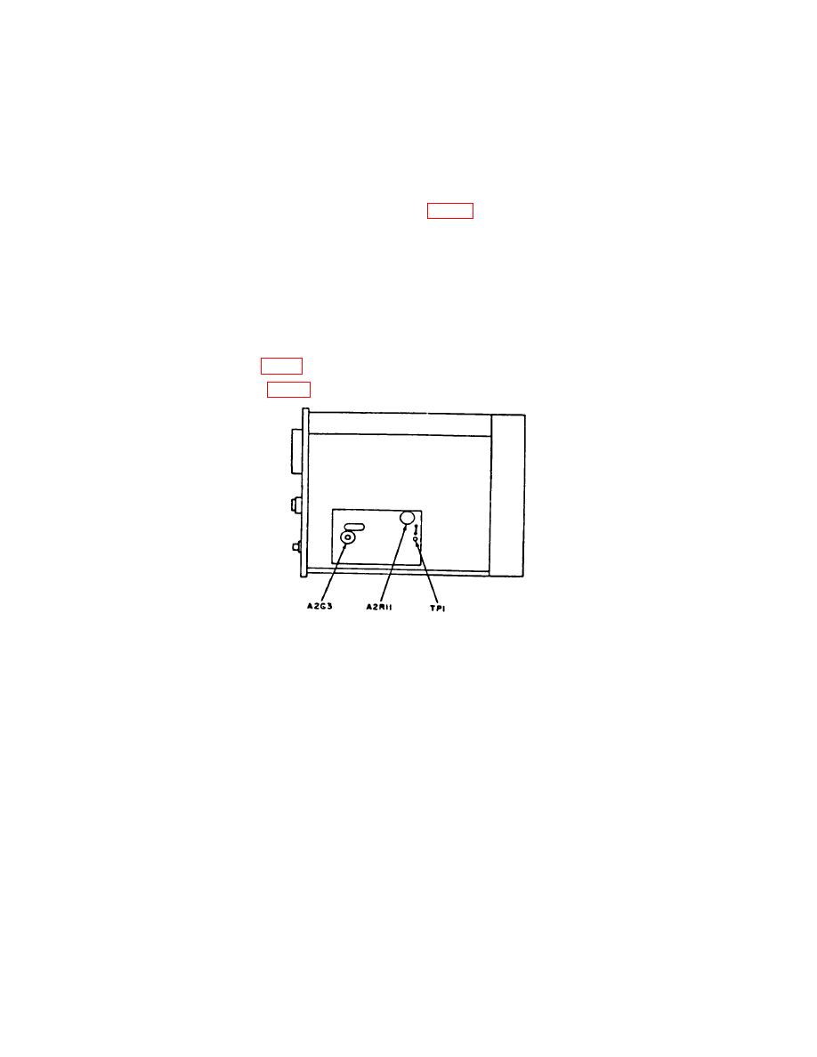
b. Adjustments
21. Audio Oscillator
a. Performance Check
(1) Position controls as listed in (a) through (d) below:
(a) MODULATION SELECTOR switch to INT 400∼.
(b) MODULATION AMPLITUDE control fully ccw.
(c) CRYSTAL CALIBRATOR switch to OFF.
(d) RANGE switch to 530KC-1800K C.
(2) Connect frequency counter to MODULATION INPUT-OUTPUT. If frequency
counter does not indicate between 380 and 420 Hz, perform b below.
(3) Set MODULATION SELECTOR switch to INT 1000∼. Frequency counter will
indicate between 950 and 1050 Hz.

