
TB 9-6625-1999-35
slowly adjust in opposite direction until oscilloscope indication just collapses (R).
25. Maximum Carrier and Modulation Zero Set
a. Performance Check
(1) Connect true rms voltmeter to RF OUTPUT 50Ω.
CAUTION
Throughout procedure, adjust ATTENUATOR VERNIER
control fully ccw before changing RANGE switch setting.
(2) Position controls as listed in (a) through (c) below:
(a) RANGE switch to 50KC-170KC.
(b) ATTENUATOR VERNIER control fully cw.
(c) MODULATION SELECTOR switch to EXT. AC.
(3) Rotate FREQUENCY control throughout range and record minimum voltage
indicated on true rms voltmeter.
(4) Repeat technique of (3) above for all RANGE switch settings. Minimum voltage
will be at least 1.05 V ac. Record minimum voltage.
(5) Set RANGE switch and adjust FREQUENCY control to value recorded in (4) above.
(6) Set MODULATION SELECTOR switch to CW. If true rms voltmeter indicates
a change in voltage output, perform b below.
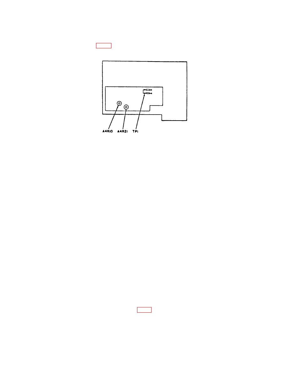
b. Adjustments
(2) Set MODULATION SELECTOR switch to EXT. AC.

