
TB 9-6625-2004-35
scale indication on TI DEVIATION meter. If measuring receiver does not indicate between
19.25 and 20.75 kHz, perform b below.
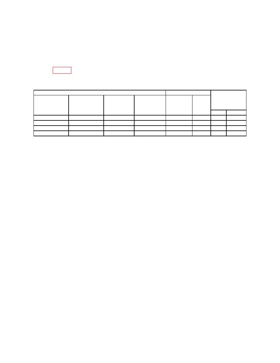
(9) Repeat technique of (2) through (8) above for control settings and indications
listed in table 5. If measuring receiver does not indicate within limits specified, perform b
below.
Test instrument
Signal generator
Measuring
receiver
FREQUENCY
DEVIATION DEVIATION
FREQUENCY-
Mod
indications
Frequency
RANGE KC
RANGE-MC
meter
MC
freq
(kHz)
(MHz)
switch
switch
indications
dial settings
(kHz)
settings
settings
(kHz)
Min
Max
55-120
100
50
50
100
1
48
52
120-250
200
100
100
200
1
95
105
250-500
400
300
300
400
1
285
315
500-1000
750
1000
300
750
1
200
400
1
1Deviation
limitation of measuring receiver.
b. Adjustments
(1) Set FREQUENCY RANGE-MC switch to 55-120 and DEVIATION RANGE KC
switch to 50.
(2) Set signal generator frequency to 100 MHz.
(3) Adjust TUNING knob for a 0 indication on CARRIER SHIFT meter.
(4) Adjust signal generator FM internal modulation frequency for a 50 kHz
indication on measuring receiver.
(5) Adjust CAL ADJ (front panel) for a 50 kHz indication on DEVIATION meter (R).
12. Audio Output
a. Performance Check
(1) Connect multimeter INPUT HI and LO to TI AUDIO OUTPUT.
(2) Set multimeter to measure volts ac.
(3) Set DEVIATION RANGE KC switch to 50 and FREQUENCY RANGE-MC
switch to 20-55.
(4) Set signal generator for a 50 MHz, 100 mV output and FM internal modulation
frequency to 20 kHz.
(5) Adjust signal generator FM internal modulation frequency for a 40 kHz
indication on TI DEVIATION meter. If multimeter does not indicate 1 V rms, perform b
below.
b. Adjustments. Adjust AUDIO ADJ (front panel) for a 1 V rms indication on
multimeter (R).

