
TB 9-6625-2009-24
k. Repeat h and i above.
8. Frequency Calibration
a. Performance Check
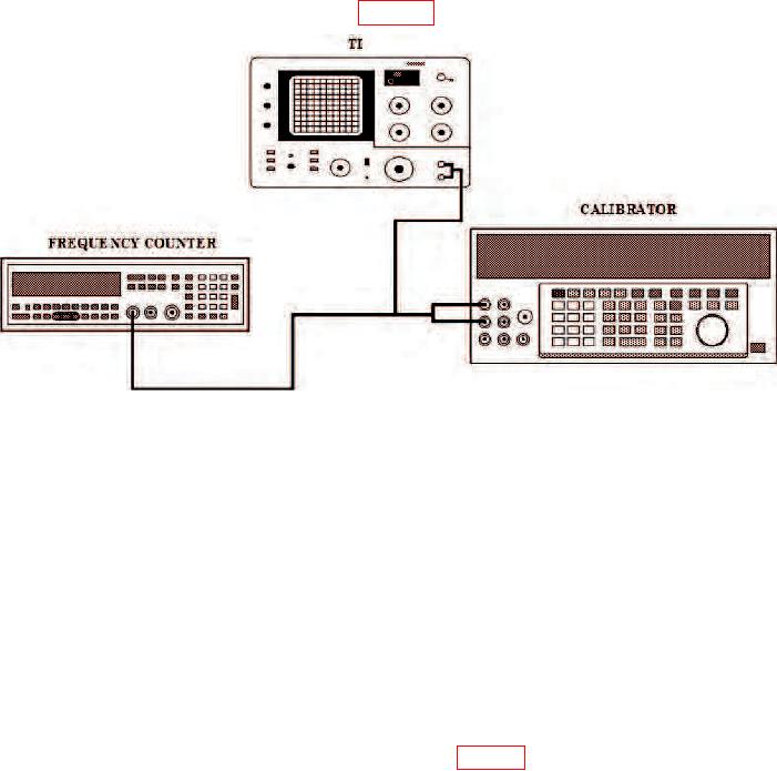
(1) Connect equipment as shown in figure 1.
Figure 1. Frequency calibration - equipment setup.
(2) Position controls as listed in (a) through (h) below.
(a) AMPLITUDE MODE LOG 10 dB/DIV pushbutton pressed.
(b) FREQUENCY control to 00.0 Hz.
(c) RESOLUTION BANDWIDTH control to 30 Hz (or as required).
(d) START/CTR switch to CTR.
(e) FREQ SPAN/DIV control as required.
(f) SWEEP TIME/DIV control to .2 SEC.
(g) ZERO CAL control for maximum display at center line.
(h) INPUT SENSITIVITY switch to 0 (zero) dBv.
(3) Adjust calibrator output control to 0.3 V rms (0 (zero) dBm).
calibrator controls to peak signal pip on center of TI display. Frequency counter will
indicate within limits specified.

