
TB 9-6625-2011-35
b. Press LINE pushbutton to ON and allow at least 30 minutes for TI to reach
operating temperature.
8. Repetition Rate
a. Performance Check
(1) Position controls as listed in (a) through (k) below:
(a) PULSE PERIOD(S) switch to 20n-1 and VERNIER control fully ccw.
(b) PULSE DOUBLE/NORM switch to NORM.
(c) PULSE DELAY(S) switch to 35n-1 and VERNIER control fully ccw.
(d) PULSE WIDTH(S) switch to 10n-1 and VERNIER control fully ccw.
(e) AMPLITUDE (negative) switch to 5.0-2.0 and VERNIER control fully
cw.
(f)
OFFSET (negative) switch to OFF
(g)
AMPLITUDE (positive) switch to 5.0-2.0 and VERNIER control fully cw.
(h)
OFFSET (positive) switch to OFF
(i)
NORM/COMPL switch to NORM.
(j)
INT LOAD switch to IN.
(k)
EXT WIDTH/NORM/RZ switch (rear panel) to NORM.
(2) Connect TRIGGER OUTPUT to frequency counter. If frequency counter
does not indicate greater than 50 MHz, perform b below.
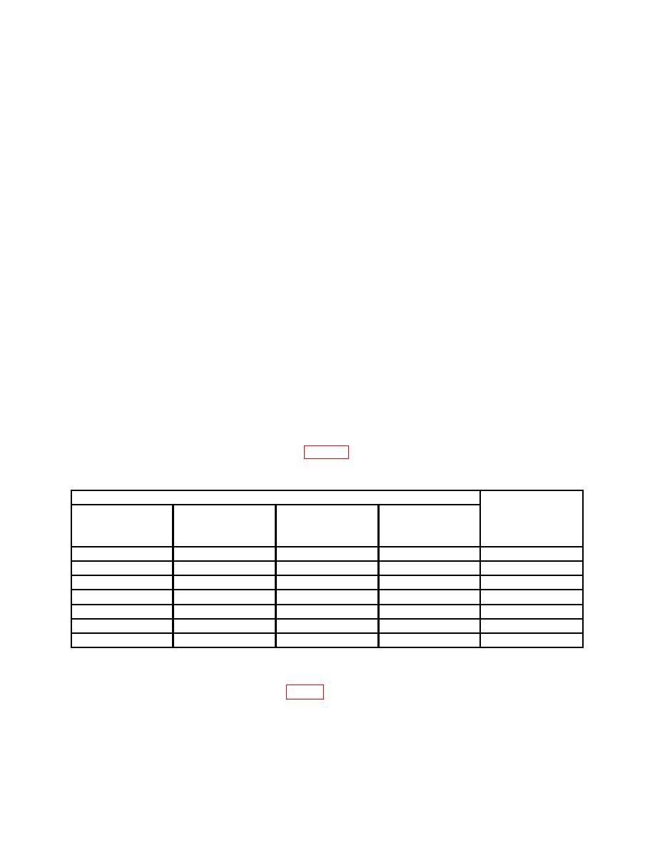
(3) Position controls as listed in table 3. Frequency counter will indicate within
limit specified.
Test Instrument
PULSE
PULSE PERIOD
PULSE
PULSE WIDTH
Frequency
PERIOD(S)
VERNIER
WIDTH(S)
VERNIER
counter
switch settings
control positions
switch settings
control positions
indications
20n - 1
10n - 1
cw
ccw
<1 MHz
1 - .1 m
10n - 1
ccw
ccw
>1 MHz
1 - .1 m
1 - .1 m
cw
ccw
<10 kHz
1 - .1 m
.1 m - 10m
ccw
ccw
>10 kHz
.1 m - 10m 1
cw
.1m - 10m
ccw
>10 ms
10m - 1
ccw
.1m - 10m
ccw
<10 ms
10m - 1
cw
10m - 1
Center
>1 s
1Set
frequency counter for time measurement, dc coupling, single ON, Holdoff ON, set input trigger level to 1.0 V and
press restart to begin measurement.
counter (R).

