
TB 9-6625-2024-24
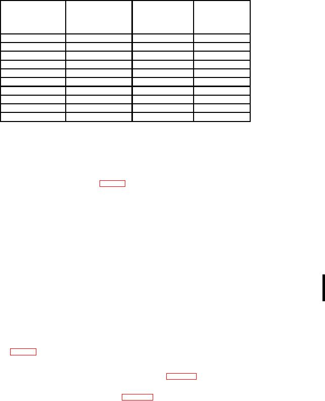
Table 5. Attenuation Check
Oscilloscope
Oscilloscope
calibrator err
Test instrument
Oscilloscope
vertical
VOLTS/DIV
display limits
calibrator voltage
deflection
switch settings
output
(divisions)
r%
5 mV
20 mV
4
2
20 mV
0.1 V
5
2
50 mV
0.2 V
4
2
0.1 V
0.5 V
5
2
0.2 V
1 V
5
2
0.5 V
2 V
4
2
1V
5 V
5
2
2V
10 V
5
2
5V
20 V
4
2
10 V
40 V
4
2
b. Adjustments
(1) Rotate oscilloscope calibrator knob located below EDIT FIELD pushbutton for
an indication of 0.0% on err display.
(2) Adjust R245 (X10 GAIN) (fig. 3) for oscilloscope indication of 5 divisions of
vertical deflection (R).
17. Attenuator Compensation
a. Performance Check
(1) Set VOLTS-TS/DIV switch to 5 mV.
(2) Connect oscilloscope calibrator SOURCE/MEASURE CHAN 1 to TI INPUT,
using 5 to 80 pF standardizer.
(3) Set oscilloscope calibrator VOLTAGE output to 1 kHz and rotate oscilloscope
calibrator knob located below EDIT FIELD pushbutton for 6 divisions of display on
oscilloscope.
(4) Set dual time base TIME/DIV OR DLY TIME switches to .2 ms.
(5) Adjust standardizer for optimum square wave display on oscilloscope. If
standardizer has insufficient range, then it will be necessary to remove TI from mainframe
to adjust C100 (fig. 3) to midrange, reinstall TI, then readjust standardizer for optimum
square wave (R).
(6) Set VOLTS/DIV switch to positions listed in table 6 and repeat technique of (3)
above. If oscilloscope does not display an optimum square wave at each switch position,
perform the appropriate adjustment listed in table 6.
CHANGE 1 15

