
TB 9-6625-2024-35
(7) Press VERT MODE LEFT pushbutton.
(8) Adjust calibration adapter AMPLITUDE and POSITION controls for a 6
division display centered vertically on crt.
(9) Adjust dual time base TIME/DIV or DLY TIME switches for .05 s and
LEVEL control for a stable display triggered on rising portion of pulse. If displayed
pulse does not have a square leading corner and a flat top with aberrations within 0.5
minor division, perform b below.
(10) Measure risetime using standard risetime technique. Risetime will be 3.5 ns
or less.
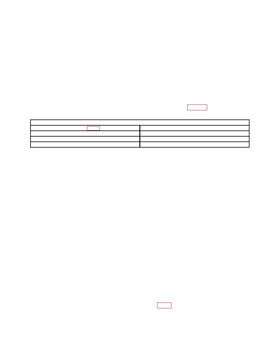
Test instrument
Adjustments (fig. 2) (R)
Area of pulse most affected
C420 and R421
1st 50 ns
R425 and C425
1st 20 ns
C427 and R427
1st 5 ns
NOTE
Due to slight differences in electrical characteristics of the
left and right vertical compartments, it may be necessary to
press VERT MODE RIGHT pushbutton and repeat a(2), (4),
and (5), and b above for best intolerance compromise.
11. Horizontal Amplifier Gain
a. Performance Check
(1) Install dual time base in left vertical compartment and calibration adapter in
horizontal (right) compartment.
(2) Adjust calibration adapter TEST switch, VERT OR HORIZ GAIN, and REP
RATE control to 100 kHz.
(3) Set dual time base TIME/DIV OR DLY TIME switch to 0.1 s and press
MAG pushbutton to X1 (IN) .
(4) Adjust calibration adapter and dual time base POSITION controls to align
bright trace on center vertical graticule line. If TI does not display 1 trace within 0.5
minor division of each vertical graticule line, perform b(1) below.
(5) Set calibration adapter TEST switch to VERT OR HORIZ COM MODE. If
trace is not aligned on center vertical line within 1 minor division, perform b(2) and (3)
below.
b. Adjustments
(1) Adjust R509 (R512 for Tektronix 7603) (fig. 1) for display of 1 trace for each
vertical graticule line (R).

