
TB 9-6625-2043-24
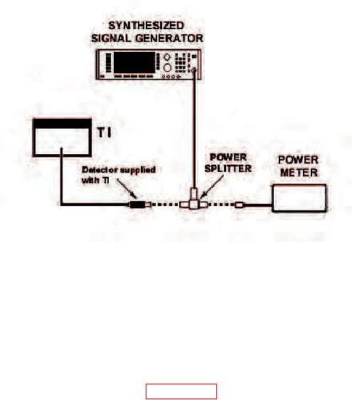
Figure 4. RF calibration - equipment setup.
(7 GHz for model 41-4A).
(3) Determine calibration factor of thermistor mount (p/o power meter) at 10 GHz (7
GHz for model 41-4A) from calibration data label.
(4) Set CALIB FACTOR control of power meter to appropriate value.
(5) Determine calibration factor of TI power detector from calibration chart attached
to detector. Set CAL FACTOR control to this value
(6) Zero TI meter as described in paragraph 7 h above.
(7) Set FULL SCALE switch to 0 dBm and OFF-PWR-dBm switch to dBm.
(8) Set synthesized signal generator output ON and adjust level control for a -1
dBm indication on power meter. TI meter will indicate between -1.41 and -0.59 dBm.
Record TI indication.
(9) Reverse connection of power meter thermistor mount and TI power detectors at
power splitter and repeat (3) through (8) above. Average of two values will be within
limits specified.
(10) Repeat (2) through (9) above at 5 and 1 GHz.
TI meter will indicate
between -1.31 and -0.69 (-1.21 and -0.79 dBm), respectively.
b. Adjustments. No adjustments can be made.
11

