
TB 9-6625-2044-35
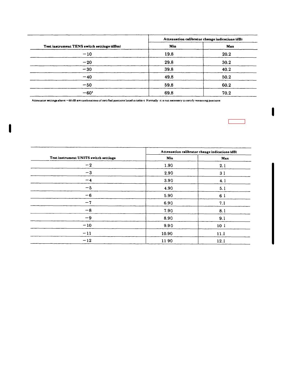
Table 4. TENS Attenuator Accuracy
(8) Set TI TENS switch to +10 and note
and 1.1 dB.
reference measurement set in (5) above.
(10) Repeat technique of (9) above for TI
(9) Set TI UNITS switch to -1. Attenuation
switch settings and indications listed in table 5.
calibrator (A1) will indicate a change of between .90
Table 5. UNITS Attenuator Accuracy
(H75-478A) with cable
b. Adjustments. No adjustments can be made.
(3) Set spectrum analyzer (A7) SCAN MODE
10.
Output Flatness
switch to MAN and adjust frequency for 1-MHz
a. Performance Check
indication on TI.
(1) Position TI controls as listed in (a) through
(4) Adjust TI output attenuation for a 0-dB
(d) below:
reference on power meter
(a) Attenuator switches to 0 dB.
(5) Slowly tune spectrum analyzer through
(b) MODE switch to SCAN HOLD.
range of 1 MHz to 110 MHz while observing power
(c) MARKER POSITION control fully
meter.
Power meter will indicate 0 dB +0.5 dB
ccw.
throughout frequency range.
(d) FUNCTION switch to TRACK
b. Adjustments. No adjustments can be made.
ANALYZER.
NOTE
11.
External Input Sensitivity
FUNCTION switch not included on some
a. Performance Check
models
(2) Connect TI RF OUT to power meter (A5),
(1) Set TI MODE switch to EXTERNAL.
using
adapter
(B2)
and
thermistor
mount
Change 1 7

