
TB 9-6625-2049-24
20. Power Supply
NOTE
Do not perform power supply check if all other parameters are
within tolerance.
a. Performance Check
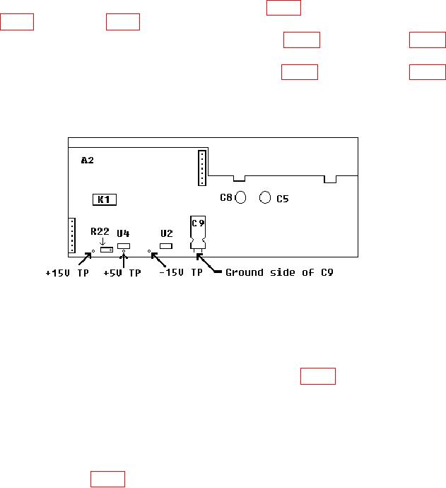
(1) Connect multimeter INPUT HI to -15 V TP (fig. 5) below and LO to ground side
multimeter does not indicate between 14.9 and 15.1 V dc.
multimeter does not indicate between 5.01 and 5.05 V dc.
(4) Repeat (1) through (3) above for best in-tolerance condition on all test points.
Figure 5. Power supply assembly A2 test instrument top view.
(5) Press presently active FUNCTION key to remove ac output and activate
ENTRY DC OFFSET key (lit).
(6) Enter 0 VOLT using DATA keys and press AMPTD CAL key.
(7) Connect multimeter INPUT HI to TP AMP OUT (fig. 3) and LO to circuit
board ground.
NOTE
The voltages measured in (1) through (3) above may be
adjusted out of tolerance by (8) through (11) below. This is not
a cause for concern.
(8) Adjust R40 (fig. 3) until digital multimeter indicates less than 5 mV dc (R).
f
(9) Connect multimeter INPUT HI and LO to TI SIGNAL.
Do not use 50
eedthrough termination.
(10) Enter 5 VOLT using DATA keys.

