
TB 9-6625-2050-24
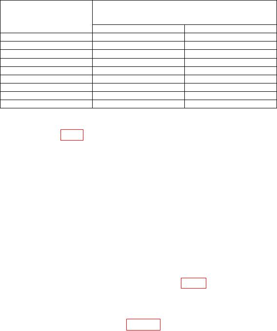
Table 6. Instrument Accuracy (Model 435A, 435B, 435BOPT001, and 435BE21)
Test instrument and
range calibrator
Multimeter indications
RANGE switch positions
(mV)
(mW)
Min
Max
W
978
1022
10
W
981
1019
30
W
984
1016
100
W
987
1013
300
1 mW
998
1002
3 mW
990
1010
10
mW
990
1010
30
mW
990
1010
100
mW
990
1010
b. Adjustments
(1) Adjust A4R35 (fig. 2) for a 1 V indication on TI meter.
(2) Set TI LINE switch to OFF. If TI meter does not indicate 0 (zero), adjust to 0
using adjustment screw located below meter face.
(3) Set switches as listed in (a) through (d) below:
(a) CAL FACTOR % to 100.
(b) RANGE to 100 mW.
(c) POWER REF (rear panel) to OFF.
(d) LINE to ON.
(4) Set range calibrator switches as listed in (a) through (c) below:
(a) RANGE to 1 mW.
(b) FUNCTION to STANDBY.
(c) POLARITY to NORMAL.
(5) Connect frequency counter between A4TP8 (fig. 2) and ground. If frequency
counter does not indicate between 204 and 236 Hz, for model 435A, or between 208
and 232 Hz for model 435B, perform (6) through (10) below. If frequency counter is within
limits, proceed to (11) below.
(6) Connect equipment as shown in figure 3.
(7) Set range calibrator FUNCTION switch to CALIBRATE.
(8) Position oscilloscope controls as listed in (a) through (e) below:
(a) MODE CH 1 and CH 2 selected.
(b) CHOP/ALT button selected for CHOP vertical display mode.
(c) CH 1 VOLTS/DIV to 0.05 V/div and AC coupled.
(d) CH 2 VOLTS/DIV to 0.2 V/div and AC coupled.
(e) SEC/DIV to 0.5 ms/div.

