
TB 9-6625-2059-35
(7) Substitute TI for signal generator.
(8) Set TI FREQUENCY MHz switches to 100 000 0 and HI LVL - VX100 -
NORM switch to HI LVL.
(9) Adjust BFO - RF LEVEL control until TI 0-dBm light just illuminates.
Spectrum analyzer will indicate within the -2.5 dBm references established in (6) above.
(10) Set HI LVL - VX100 - NORM switch to VX100 and adjust BFO - RF LEVEL
control to -80 dBm.
(11) Set step attenuator to 40 dB. If spectrum analyzer does not indicate within
2.5 dBm references established in (6) above, perform b below.
(12) Repeat technique of (10) and (11) above for BFO - RF LEVEL control settings
listed in table 10. Spectrum analyzer will indicate within 2.5 dBm references established
in (6) above.
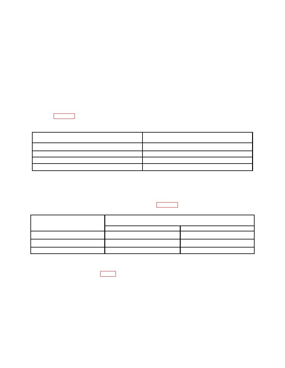
Test instrument
BFO - RF LEVEL control settings
Step attenuator settings
90
30
100
20
110
10
120
0
(13) Set HI LVL - VX100 - NORM switch to NORM and BFO -RF LEVEL control
to -80 dBm. Spectrum analyzer will indicate within 2.5 dBm references established in (6)
above.
(14) Repeat technique of (1) through (13) above for FREQUENCY MHz switch
settings and spectrum analyzer indications listed in table 11.
Test instrument
Spectrum analyzer indications
FREQUENCY MHz switch
settings
Min
Max
250
-4.0
+4.0
500
-6.0
+6.0
900
-6.0
+6.0
b. Adjustments
(1) Adjust A1A1R43 (fig. 3) until spectrum analyzer indicates signal at the reference
established in a (5) above (R).
(2) This adjustment may have to be set for best in-tolerance compromise between
100 and 999 MHz.
17

