
TB 9-6625-2071-24
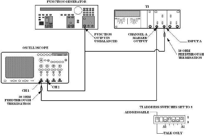
Figure 2. Remote Trigger Level - Equipment Setup.
(2) Set oscilloscope channel 1 for DC input coupling, 1 MΩ input, 500mV/div
amplitude and 2 ms/div sweep.
(3) Turn oscilloscope channel 2 to on and set channel 2 for AC input coupling, 1 MΩ
input and 1 V/div amplitude.
(4) Set oscilloscope triggering for positive slope, auto level, channel 2 source
and DC coupling.
(5) Set function generator as listed in (a) through (e) below:
(a)
Function to sine wave.
(b)
Frequency to 100 Hz.
(c)
Offset to 0 V dc.
(d)
Function Outputs to 50 Ω.
(e)
Amplitude for a 6 Vp-p display on oscilloscope CH 2.
(6) Execute TI command string: PF4G6S1S3A379+000*B37+000*R.
13

