
TB 9-6625-2077-24
(8) Adjust A6R31 (fig. 1) for a +3.00 dBm indication on TI RF OUTPUT meter (R).
(9) Adjust RF OUTPUT LEVEL control for a -7.00 dBm indication on
measuring receiver.
(10) Adjust A6R25 (fig. 1) for a -7 dBm indication on TI RF OUTPUT meter (R).
(11) Set POWER switch to OFF and reinstall assembly A6 and extender board (fig. 1)
in proper locations.
(12) Set POWER switch to ON.
10. Frequency Modulation
a. Performance Check
(1) Position controls as listed in (a) through (d) below:
(a) RF OUTPUT switch to +10 dBm.
(b) TUNING RANGE switch to 16-90 MHz (16-80 MHz).
(c) MODULATION switch to FM 150 Hz.
(d) FM METER RANGE switch to 10 kHz.
(2) Connect TI RF OUTPUT to measuring receiver power sensor.
(3) Adjust TUNING COARSE and FINE controls for an indication of 20.00 MHz
on FREQUENCY display.
(4) Set measuring receiver to frequency counter mode to determine the
center frequency.
(5) Adjust RF OUTPUT LEVEL control for a 0 dBm indication on TI RF
OUTPUT meter.
(6) Adjust MODULATION LEVEL control for a 10 kHz indication on TI
MODULATION meter.
(7) Set measuring receiver controls to measure modulation rate. If measuring
receiver does not indicate within limits specified in first row of table 7, perform b below.
(8) Repeat technique of (1) (c), (1) (d) and (4) through (6) above for the remainder of
MODULATION switch settings and MODULATION meter indications listed in table 7. If
measuring receiver does not indicate within limits specified in table 7, perform b below.
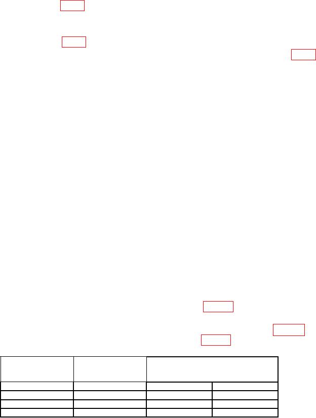
Table 7. Modulation Frequency
Test instrument
Test instrument
Measuring receiver
MODULATION
MODULATION
indications
switch setting
meter indications
(Hz)
(Hz)
(kHz)
Min
Max
150
10
149.000
151.000
400
10
395.00
405.000
1000
15
950.00
1050.00
(9) Adjust MODULATION
LEVEL
control
for
10
kHz
indication
on
MODULATION meter.
(10) Set measuring receiver to measure FM deviation.

