
TB 9-6625-2077-35
(4) Adjust RF OUTPUT LEVEL control for a 0 dBm indication on TI RF
OUTPUT meter.
(5) Set measuring receiver to read FM deviation.
(6) Adjust MODULATION LEVEL control for a 10 kHz indication on TI
MODULATION meter.
(7) Set measuring receiver controls to measure FM and audio analyzer controls to
measure frequency. If audio analyzer does not indicate between the values listed in table 7
for the MODULATION switch setting, perform b below.
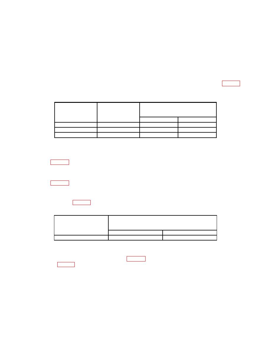
Test instrument
Test instrument
Audio analyzer
MODULATION
MODULATION
indications
switch setting
meter indications
(Hz)
(Hz)
(kHz)
Min
Max
150
10
149.000
151.000
400
10
395.00
405.000
1000
15
950.00
1050.00
(8) Set MODULATION switch to FM 400 Hz.
(9) Repeat (4) and (5) above. If audio analyzer does not indicate between the values
listed in table 7 for the MODULATION switch setting, perform b below.
(10) Set MODULATION switch to FM 1 KHz.
(11) Repeat (4) and (5) above. If audio analyzer does not indicate between the values
listed in table 7 for the MODULATION switch setting, perform b below.
(12) Adjust MODULATION LEVEL control for 10 kHz indication on
MODULATION meter. If measuring receiver deviation does not indicate between the
values specified in table 8, perform b below.
Test instrument
MODULATION
Measuring receiver indications
meter indications
(kHz)
kHz
Min
Max
10
8.5
11.5
(13) Set FM METER RANGE switch to 75 kHz and adjust MODULATION
specified in table 9, perform b below.
10

