
TB 9-6625-2077-35
(22) Set POWER switch to OFF and disconnect test equipment.
(23) Reinstall assembly A5 and extender board (fig. 1) in proper locations.
(24) Set POWER switch to ON.
11. Amplitude Modulation
a. Performance Check
(1) Position controls as listed in (a) through (c) below:
(a) RF OUTPUT switch to +10 dBm.
(b) TUNING RANGE switch to 4-20 MHz.
(c) MODULATION switch to AM 1 kHz.
(2) Connect TI RF OUTPUT to measuring receiver power sensor and set controls to
measure AM. Connect measuring receiver MODULATION OUTPUT/AUDIO INPUT to
audio analyzer INPUT HIGH and set controls to measure distortion.
(3) Adjust TUNING COARSE and FINE controls for an indication of 10.00 MHz
on FREQUENCY display.
(4) Adjust RF OUTPUT LEVEL control for a 0 dBm indication on TI RF
OUTPUT meter.
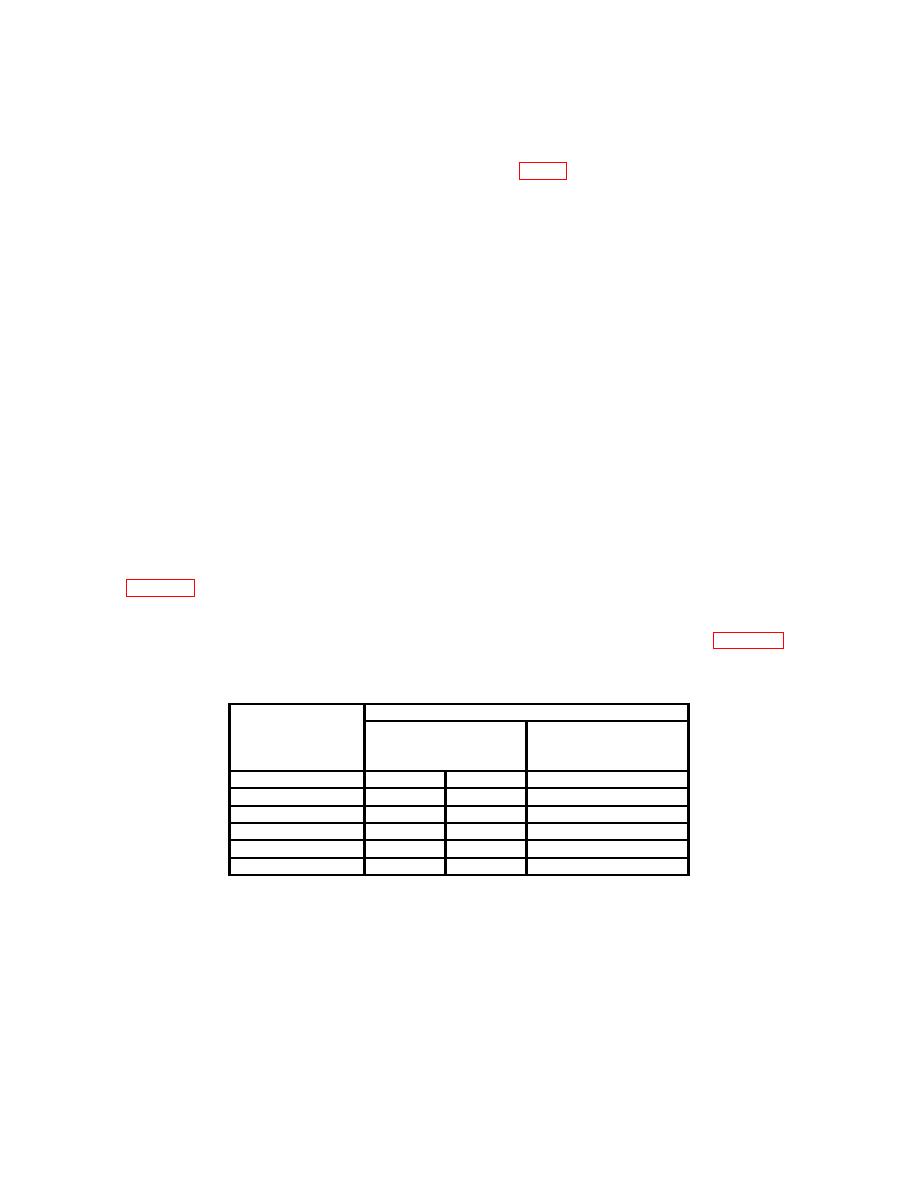
(5) Adjust MODULATION LEVEL control for 20 percent modulation on TI
MODULATION meter. If measuring receiver does not indicate between the values listed
in table 11 for the MODULATION LEVEL setting, perform b below.
(6) Audio analyzer will indicate 1 percent distortion or less.
(7) Repeat technique of (5) and (6) above for indications listed in table 11.
If
measuring receiver indications are not within limits specified, perform b below.
Signal generator
Test instrument
Measuring receiver
Audio analyzer
modulation
indications
distortion indications
(%)
(%)
(%)
Min
Max
20
18.80
21.20
<1
40
37.6
42.4
<1
60
56.4
63.6
<3
80
75.2
84.8
<3
90
84.6
95.4
<3
b. Adjustments
(1) Position controls as listed in (a) through (e) below:
(a) MODULATION switch to AM 1 KHz.

