
TB 9-6625-2083-24
(2) Rotate oscilloscope calibrator knob located below EDIT FIELD pushbutton for
an Err display readout of 0.0%, and adjust R269 CH 1 GAIN (fig. 9) (accessible without
removing case) for 6 divisions of display on TI (R).
37. Vertical Volts Readout
a. Performance Check
(1) Position controls as listed in (a) through (d) below:
(a) CH 1 and CH 2 VOLTS/DIV switches to .5 m.
(b) CH 1 and CH 2 AC-GND-DC switches to GND.
(c) STORAGE MODE NORM pushbutton pressed.
(d) CURSOR FUNCTION VOLTS pushbutton pressed.
(2) Adjust CURSOR/NO. OF SWEEPS control to obtain 6 divisions between
VOLTS CURSORS. If readout is not within limits specified in first row of table 15,
perform b below.
(3) Adjust CH 1 VOLTS/DIV VAR control out of calibrated detent position.
Readout will be between 5.88 and 6.12 divisions. Return CH 1 VOLTS/DIV VAR control
to calibrated detent position.
(4) Repeat technique of (2) above for VOLTS/DIV switch settings listed in table 15.
Indications will be within limits specified in table 15.
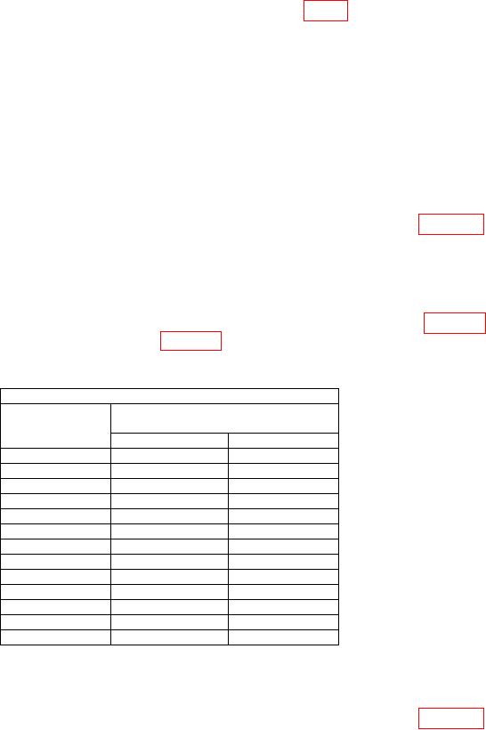
Table 15. Volts Cursor Readout Accuracy CH1
Test instrument
VOLTS/DIV
LED readout indication limits
switch setting
Min
Max
0.5 mV
2.94 mV
3.06 mV
1 mV
5.88 mV
6.12 mV
2 mV
11.76 mV
12.24 mV
5 mV
29.40 mV
30.60 mV
10 mV
58.8 mV
61.2 mV
20 mV
117.6 mV
122.4 mV
50 mV
294.0 mV
306.0 mV
0.1 V
0.588 V
0.612 V
0.2 V
1.176 V
1.224 V
0.5 V
2.940 V
3.060 V
1 V
5.88 V
6.12 V
2 V
11.76 V
12.24 V
5 V
29.40 V
30.60 V
(5) Set VERT MODE switch to CH 2 and release CH 1.
(6) Adjust CURSOR/NO. OF SWEEPS control to obtain 6 divisions between
VOLTS CURSORS. If readout is not within limits specified in first row of table 16,
perform b below.

