
TB 9-6625-2083-35
Test instrument
Adjust for optimum square wave display (R)
CH 1 and CH 2
VOLTS/DIV
Square corner
Flat top
switch settings
CH 1
CH 2
CH 1
CH 2
50
mV
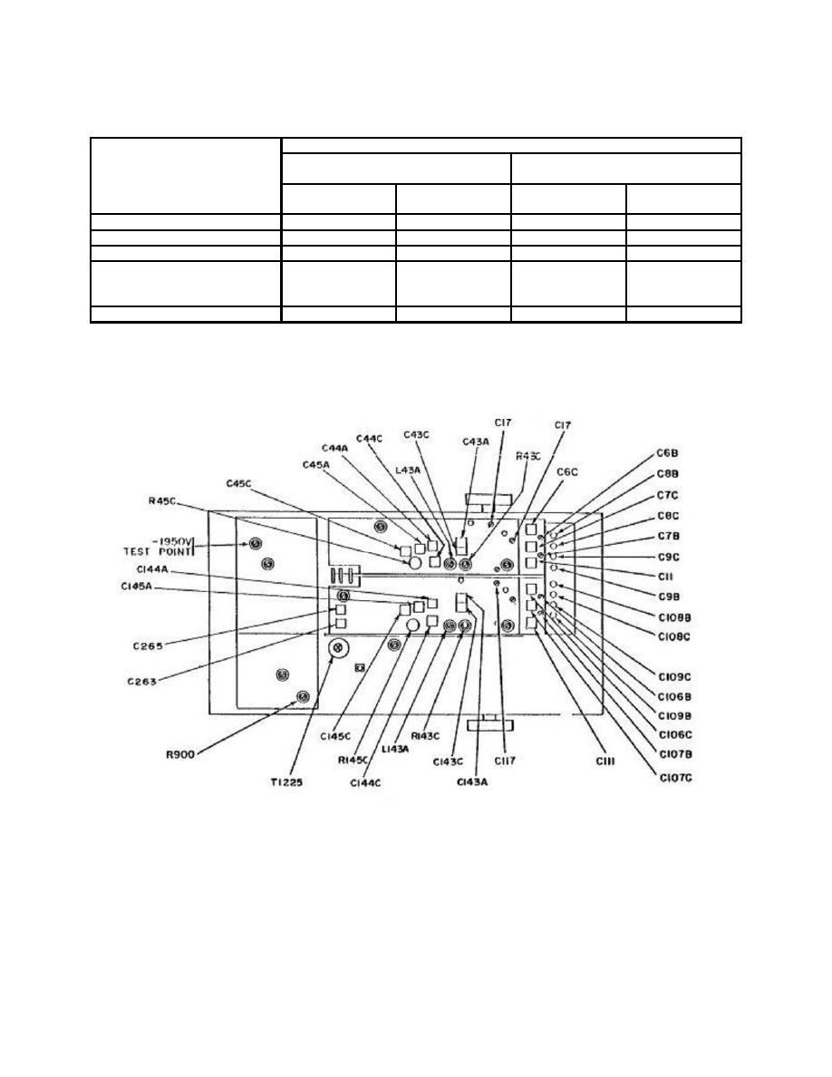
C6C
C106C
C6B
C106B
.1
C7C
C107C
C7B
C107B
.2
C8C
C108C
C8B
C108B
.5
---
---
Adjust C11
Adjust C111
---
---
for best
for best
11
compromise
compromise
2
C9C
C109C
C9B
C109B
1Remove
termination from setup and set oscilloscope calibrator VOLTAGE output to 5 V at 1 kHz.

