
TB 9-6625-2083-35
(4) Repeat technique of (3) above for VOLTS/DIV switch settings and adjustments
listed in table 9, but do not readjust standardizer.
(5) Set oscilloscope calibrator for a CHAN 2, EDGE mode output of 100 mV at 1 kHz.
(6) Set TI MODE switch to CH 2 and repeat technique of (3) and (4) above, using
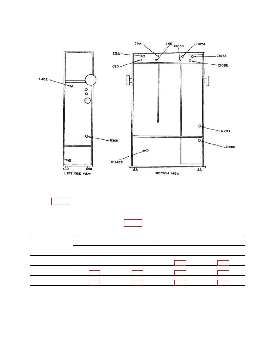
Test instrument
Adjustments (R)
VOLTS/DIV
Square corner
Flat top
switch
settings
CH 1
CH 2
CH 1
CH 2
.1
---
---
C9
C109
.2
C5D
C105D
C5A
C105A
21
C6E
C106E
C6A
C106A
1Remove
termination.
b. Adjustments. No further adjustments can be made.
25

