
TB 9-6625-2083-35
EDIT FIELD pushbutton to align one time marker per division on TI.
Oscilloscope
calibrator Err display readout will be within limits specified in table 19.
(23) Press HORIZ DISPLAY B DLY'D pushbutton and repeat technique of (22)
above for B TIME/DIV switch settings listed in table 19. Oscilloscope calibrator Err
display readout will be within limits specified in table 19.
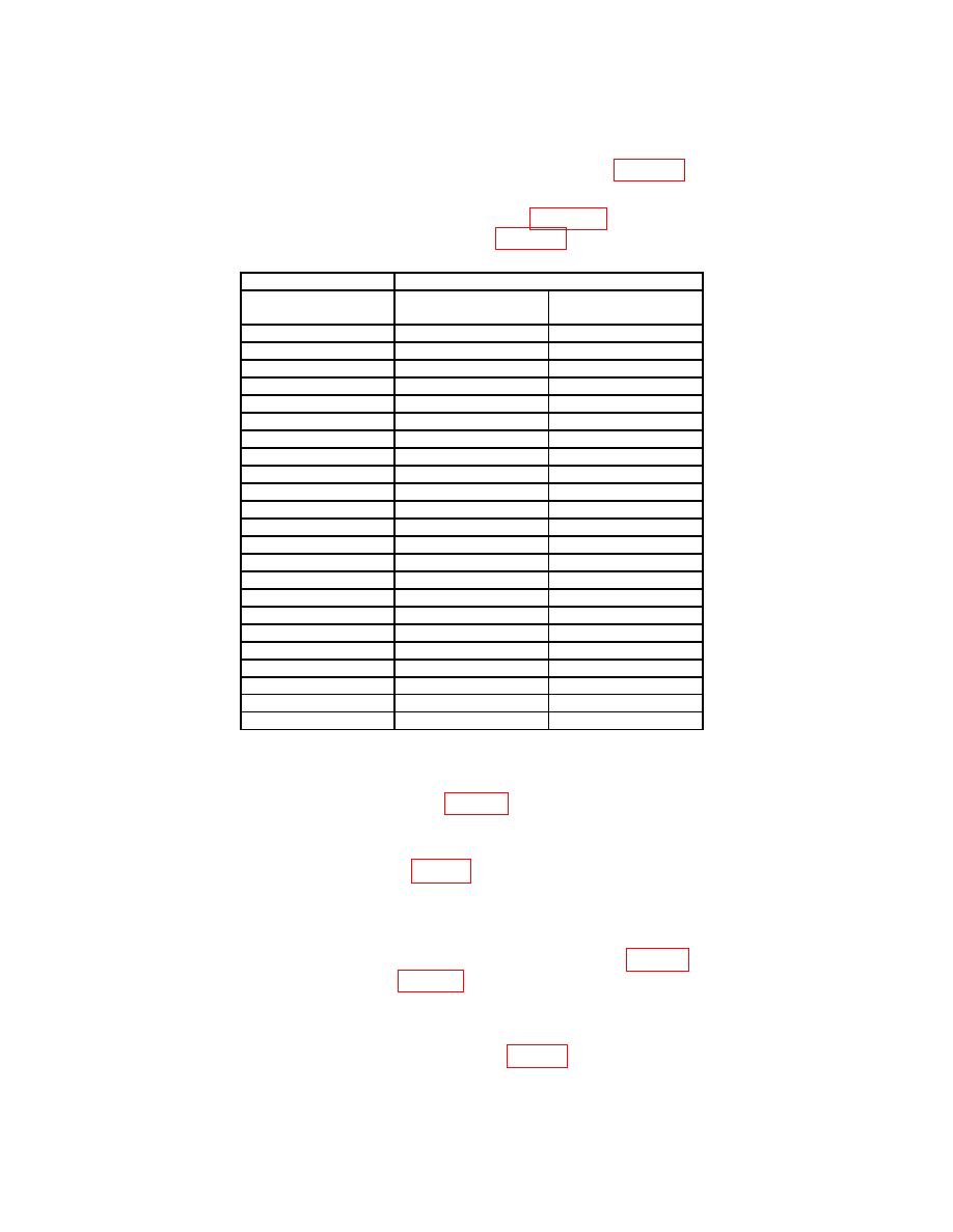
Test instrument
Oscilloscope calibrator
A AND B TIME/DIV
MARKER mode
Err display
setting
output
indication limits (%)
.02 s
20 ns
2
.05 s
50 ns
2
.1 s
.1 s
2
.2 s
.2 s
2
.5 s
.5 s
2
1
s
1 s
2
2
s
2 s
2
5
s
5 s
2
10
s
10 s
2
20
s
20 s
2
50
s
50 s
2
.1 ms
.1 ms
2
.2 ms
.2 ms
2
.5 ms
.5 ms
2
1
ms
1 ms
2
2
ms
2 ms
2
5
ms
5 ms
2
10
ms
10 ms
2
1
20
ms
20 ms
2
50
ms
50 ms
2
.1 s
.1 s
2
2
.2 s
.2 s
2
2
.5 s 2
.5 s
2
1Press
A TRIG MODE NORM pushbutton.
2A
sweep only.
b. Adjustments
(1) Adjust R970 B SWP START (fig. 12) so that intensified portion of A sweep
begins at start of 2d time marker, and pulse displayed on B DLY'D sweep starts at
beginning of sweep (R).
(2) Adjust R173 A SWP CAL (fig. 13) so that intensified portion of A sweep begins
at start of 10th time marker, and pulse displayed on B DLY'D trace starts at beginning of
sweep (R).
NOTE
Interaction exists between R970 B SWP START (fig. 12) and
R173 A SWP CAL (fig. 13). Repeat as necessary until no
further improvement is observed.
(3) Rotate oscilloscope calibrator knob located below EDIT FIELD pushbutton for
an Err display of 0.0%. Adjust R572 X1 GAIN (fig. 12) for exactly one time marker per
division (R).
44

