
TB 9-6625-2094-24
MODULATION FREQ switch to 1 kHz.
(d)
MODULATION FM/AM slide control to 3 kHz FM.
(e)
OUTPUT step attenuator switch for +10 dBm.
(f)
OUTPUT VERNIER control fully cw.
(g)
(3) Set measuring receiver to measure FM with 50 Hz high-pass filter 15 kHz low-
pass filter.
(4) Set measuring receiver to measure modulation distortion. Measuring receiver
will indicate within limit specified in first row of table 9.
(5) Set TI MODULATION MODE switch to FMx10.
Measuring receiver will
indicate within limit specified in table 9.
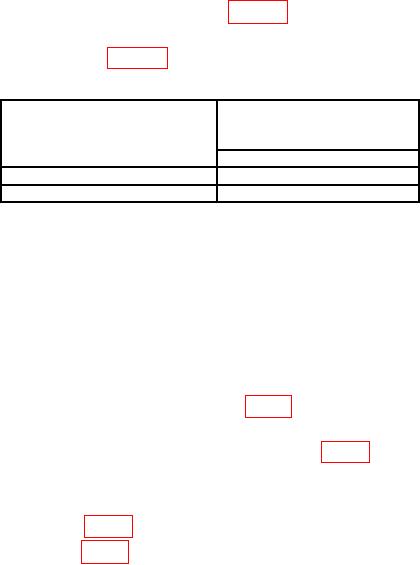
Table 9. FM Distortion
Test instrument
Measuring receiver
MODULATION MODE
indication
setting
(%)
Limit
FMx1
<4
FMx10
<2
b. Adjustments. No adjustments can be made.
17. Power Supply
a. Performance Check
NOTE
Do not perform power supply check if all other parameters are
within tolerance.
(1) Connect multimeter to pin 3 of M30-1 (fig. 1) and chassis ground. If multimeter
does not indicate +18.00 V dc, perform b (1) below.
(2) Move multimeter connection to pin 4 of M30-1 (fig. 1). If multimeter does not
indicate -18.00 V dc, perform b (2) below.
b. Adjustments.
(1) Adjust +18 V ADJ (fig. 2) for +18.00 V dc indication on multimeter (R).
(2) Adjust -18 V ADJ (fig. 2) for -18.00 V dc indication on multimeter (R).
18. Final Procedure
a. Deenergize and disconnect all equipment.
b. Annotate and affix DA label/form in accordance with TB 750-25.

