
TB 9-6625-2099-24
(13) Set oscilloscope calibrator VOLTAGE output as listed in first row of table 9.
(14) Set CH 2 VOLTS/DIV switch as listed in first row of table 9 and rotate
oscilloscope calibrator knob located below EDIT FIELD pushbutton to obtain oscilloscope
display divisions as listed in first row of table 9. Oscilloscope calibrator err display will
indicate within limits as specified in table 9; if not, perform b(5) through (12) below.
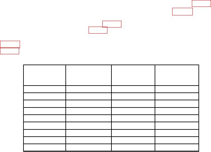
(15) Repeat technique of steps (12) through (14) above for remaining rows listed in
table 8. Oscilloscope calibrator err display indications will be within limits specified in
Table 9. CH 2 Vertical Gain
Oscilloscope
Test instrument
Oscilloscope calibrator
calibrator
VOLTS/DIV
VOLTAGE
Err display limits
Test instrument
switch settings
output
display divisions
(+%)
5
mV
20
mV
4
2
20
mV
0.1 V
5
2
50
mV
0.2
V
4
2
0.1 V
0.5
V
5
2
0.2 V
1
V
5
2
0.5 V
2
V
4
2
1
V
5
V
5
2
2
V
10
V
5
2
5
V
20
V
4
2
(16) Connect oscilloscope calibrator CHAN 1 to TI CH 1 using a 50 feedthrough
termination. Ensure oscilloscope calibrator CHAN 1 output is selected by using technique
in step (1) above.
(17) Set DISPLAY MODE switch to CH 1 and CH 1 VOLTS/DIV switch to 10 mV.
(18) Set oscilloscope calibrator to EDGE, and output a 60 mV, 1 kHz output.
(19) Adjust CH 1 POSITION and time base controls as necessary to view display.
(20) Rotate oscilloscope calibrator knob located below EDIT FIELD pushbutton to
obtain 6 divisions on oscilloscope display. If displayed waveform does not have flat tops,
perform b (13) below (CH 2, b (14) below).
(21) Remove 50 feedthrough termination from oscilloscope calibrator CHAN 1 and
TI CH 1. Reconnect oscilloscope calibrator CHAN 1 to TI CH 1 using a 5-80 pF
standardizer. Rotate oscilloscope calibrator knob located below EDIT FIELD pushbutton
to obtain 6 divisions 6 divisions of vertical display.
12

