
TB 9-6625-2099-35
(2)
TRIGGER SOURCE switch to MODE.
(3)
CH 2 POLARITY switch to +UP.
(4)
CH 1 and CH 2 POSITION controls to midrange.
(5)
CH 1 and CH 2 VOLTS/DIV switches to 10 mV.
(6)
CH 1 and CH 2 AC-GND-DC switches to DC.
(7)
CH 1 and CH 2 VOLTS/DIV VARIABLE (CAL IN) pressed to in position.
8. Vertical Gain
a. Performance Check
(1) Connect oscilloscope calibrator CHAN 1 to TI CH 1 and connect oscilloscope
calibrator CHAN 2 to TI CH2.
(2) Set oscilloscope calibrator VOLTAGE output for 50 mV at 1 kHz amplitude.
(3) Adjust TI time base controls as necessary for a stable display.
(4) Adjust TI CH 1 GAIN control (front panel) for 5 divisions of display.
rotate oscilloscope calibrator knob located below EDIT FIELD pushbutton to obtain
display will indicate within limits specified in table 3; if not, perform b below.
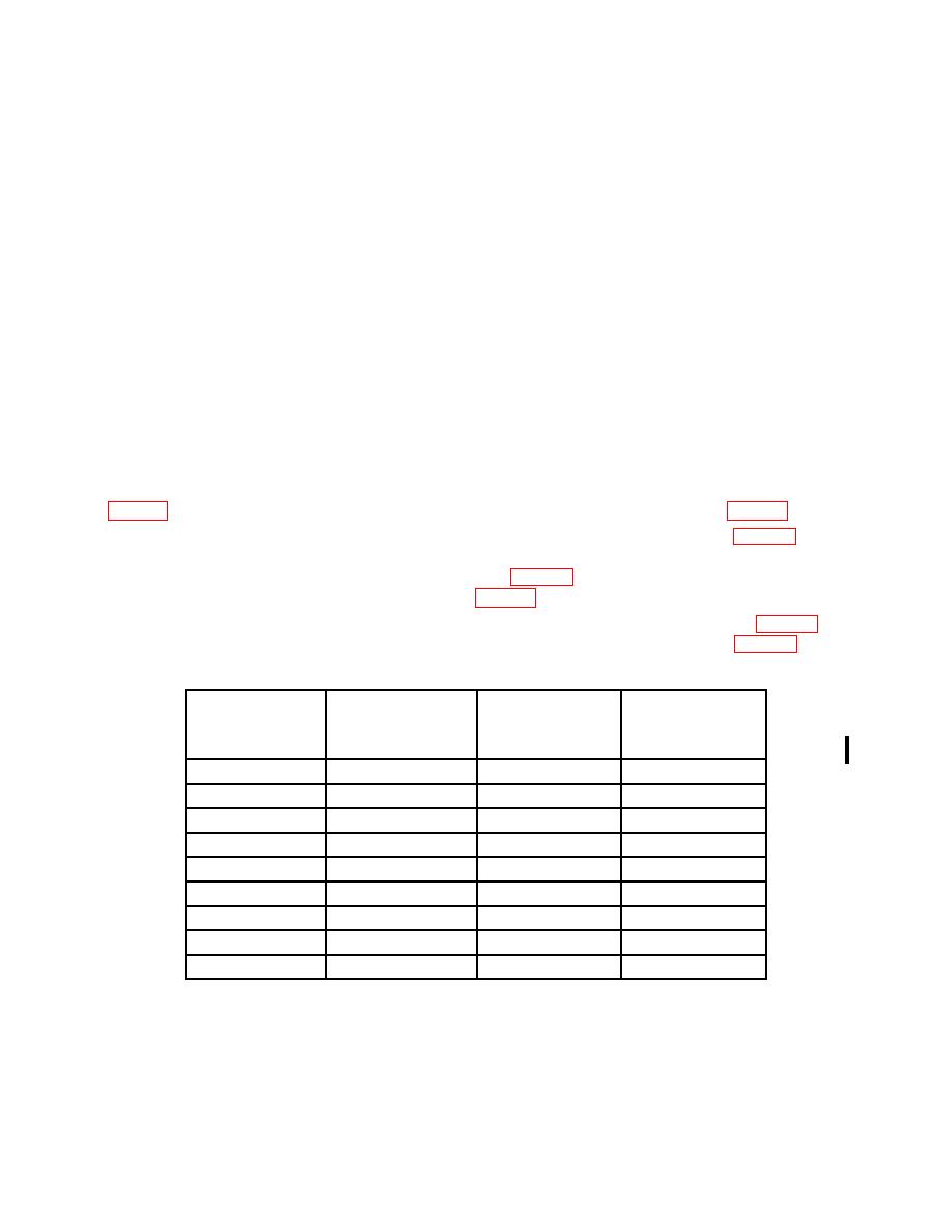
(7) Repeat technique of (3) through (6) above for remaining rows listed in table 3.
Oscilloscope calibrator err display indications will be within limits specified in table 3.
Oscilloscope
Test instrument
Oscilloscope calibrator
calibrator
VOLTS/DIV
voltage
Test instrument
Err display limits
switch settings
output
display divisions
(%)
5
mV
20
mV
4
2
20
mV
.1
V
5
2
50
mV
.2
V
4
2
.1
V
.5
V
5
2
.2
V
1
V
5
2
.5
V
2
V
4
2
1
V
5
V
5
2
2
V
10
V
5
2
5
V
20
V
4
2

