
TB 9-6625-2102-24
(13) Position TI controls as listed in (a) through (d) below:
Main generator FUNCTION switch to
.
(a)
FREQ/MULT (Hz) switch to 1K.
(b)
MODULATION AM switch to OFF.
(c)
AMPLITUDE control fully cw.
(d)
NOTE
If signal is distorted, slowly turn AMPLITUDE control ccw
until signal is no longer distorted. Overload indicator will light
when signal is distorted.
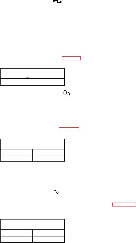
(14) If oscilloscope display is not within limits shown in table 21, perform b (3) below.
Table 21. Square Wave Amplitude
Oscilloscope indications
(>V p-p)
15
(15) Set main generator FUNCTION switch to
and adjust AMPLITUDE
control fully ccw.
(16) Disconnect TI from oscilloscope Vertical 1 input and connect TI to audio
analyzer INPUT HIGH using 50 : feedthrough termination.
(17) Initiate audio analyzer.
(18) If audio analyzer is not within limits shown in table 22, perform b (4) below.
Table 22. Sine Wave Zero
Audio analyzer indications
(V)
Min
Max
.020
.020
(19) Position TI controls as listed in (a) through (d) below:
(a) MODE switch to INT TRIG.
(b) Frequency dial to 1.0.
(c) Main generator FUNCTION switch to
.
(d) AMPLITUDE control fully cw.
(20) If audio analyzer does not indicate within limits shown in table 23,
perform b (5) below.
Table 23. Zero
Audio analyzer indications
(V)
Min
Max
-.100
.100
(21) Adjust frequency dial to 2.
15

