
TB 9-6625-2102-35
and TRIG START/STOP control to 0 CAL (ccw
(4) FUNCTION switch to
detent).
(5) ATTENUATION (dB) switch to 20/ 0 and AMPLITUDE control fully ccw.
f. Set POWER switch to ON and allow at least 30 minutes for TI to reach operating
temperature.
8. Modulation Generator Frequency
a. Performance Check
(1) Initiate audio analyzer and set to measure frequency.
(2) Connect TI MODULATION GENERATOR OUT (600 Ω) to audio analyzer
INPUT HIGH.
(3) Perform steps as listed in (a) through (c) below for each row in table 3.
(a) Set TI FREQ/PERIOD MULT (Hz/s) to switch settings.
(b) Adjust TI VARIABLE control to settings.
(c) Using audio analyzer, verify frequency indications.
NOTE
All out of tolerance indications, perform b below:
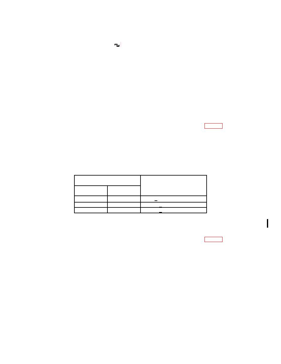
Table 3. Frequency
Test instrument
FREQ/PERIOD MULT (Hz/s)
Audio analyzer
VARIABLE
Switch
indications
control fully
settings
1K/100K
cw
> 100 kHz
-
ccw
<1
kHz
10/1k
cw
>1
kHz
(4) Disconnect TI from audio analyzer and connect to oscilloscope Vertical 1 input.
(5) Set up oscilloscope to measure frequency.
(6) Perform steps as listed in (a) through (c) below for each row in table 4.
(a) Set TI FREQ/PERIOD MULT (Hz/s) to switch settings.
(b) Adjust TI VARIABLE control to settings.
(c) Using oscilloscope, verify frequency indications.
NOTE
All out of tolerance indications, perform b below:
CHANGE 1

