
TB 9-6625-2102-35
(3) Ensure MODULATION GENERATOR, FREQ/PERIOD MULT (Hz/s) switch is
set to 10/1K and adjust VARIABLE control fully cw.
.
(4) Ensure MODULATION GENERATOR, FUNCTION switch is set to
(5) If audio analyzer does not indicate within limits in table 9, perform b below.
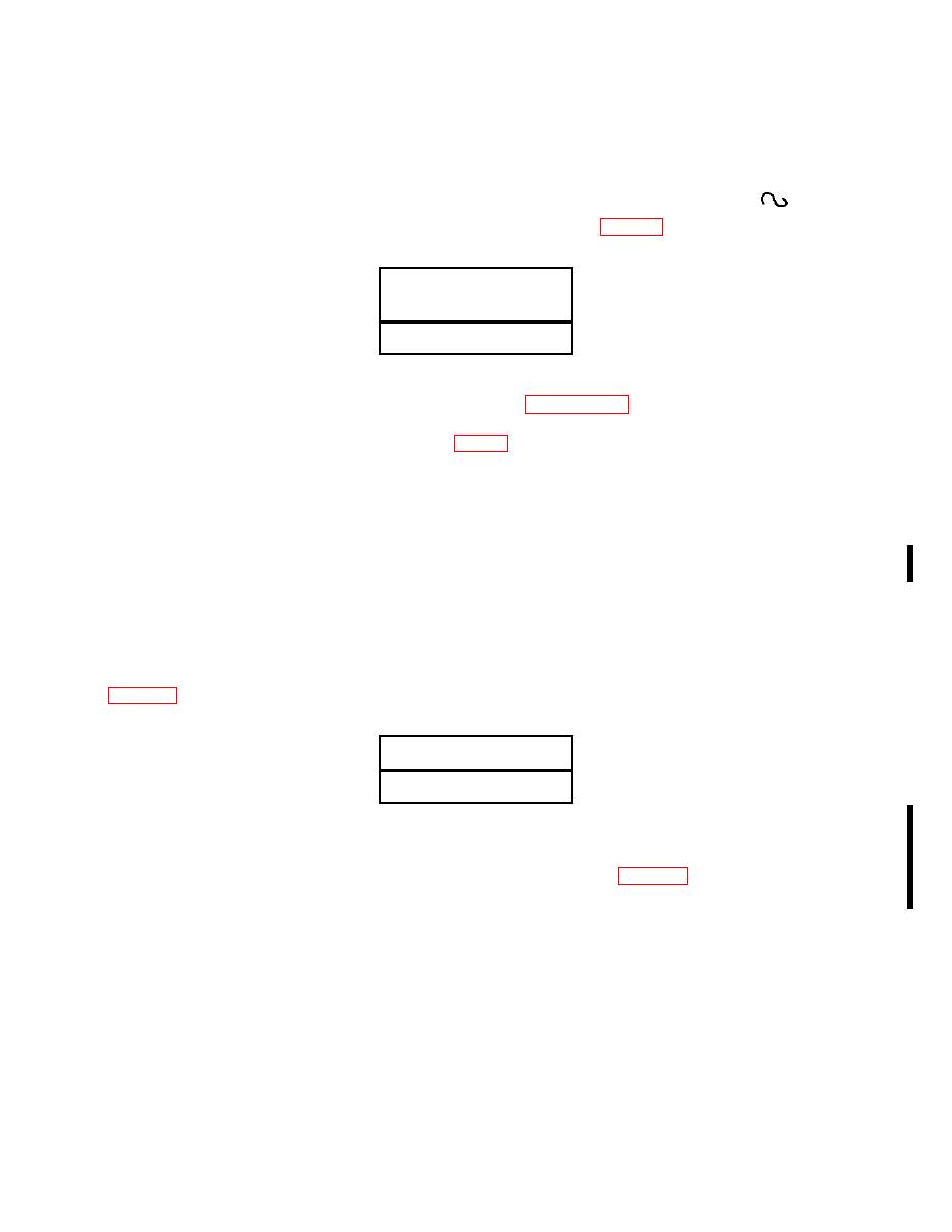
Audio analyzer distortion
indications
(<%)
5
NOTE
If adjustments are made, repeat paragraph 9 above.
less than 5 percent (R) on audio analyzer.
11. Modulation Generator Ramp
a. Performance Check
(1) Connect TI MODULATION GENERATOR OUT (600 Ω) to oscilloscope
Vertical 1 input.
(2) Set FREQ/PERIOD MULT (Hz/s) switch to 10/1k and adjust VARIABLE
control fully cw.
(3) Set TI MODULATION GENERATOR FUNCTION switch to positive going
sawtooth then negative going sawtooth. If oscilloscope does not display optimum ramps in
Optimum ramp indications
(Yes/No)
(4) Electronically ground Vertical 1 input, select dc coupling and position trace to
center horizontal line using position control.
(5) Select Vertical 1 input and, if negative peak level in table 11 does not coincide
with center horizontal center line MIN indication, perform b (3) below.
CHANGE 1

