
TB 9-6625-2114-24
receiver indication as close as possible to indication recorded in (12) above. Press measuring
receiver MEASUREMENT DISPLAY RATIO key.
(16) Set signal generator frequency to 60 MHz.
(18) Adjust signal generator amplitude for a 0.3 V ac indication on TI. Measuring
receiver will indicate within 1 dB.
(19) Repeat (16) through (18) above at 90, 150 and 250 MHz.
(20) Repeat technique of (16) through (18) above at 350, 550 and 700 MHz.
Measuring receiver will indicate within 3 dB.
b. Adjustments. No adjustments can be made.
11. Resistance
a. Performance Check
(1) Set SELECTOR switch to OHMS.
(2) Adjust OHMS ADJ for
meter indication.
(3) Short OHMS and COMMON leads together and adjust ZERO ADJ for 0 meter
indication.
(4) Separate OHMS and COMMON leads.
(5) Repeat (2) through (4) above until no further adjustment is necessary.
(6) Connect OHMS and COMMON leads to resistance standard no. 1.
(7) Set resistance standard for a 10
indication on TI.
If resistance standard
setting is not between 9 and 11 , perform b below.
(8) Disconnect TI from resistance standard.
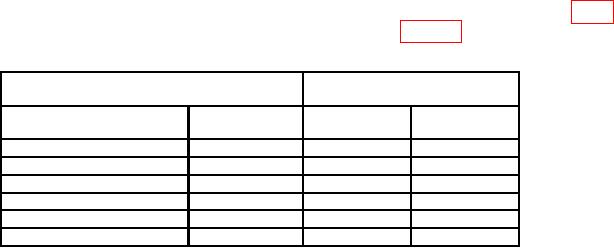
(9) Repeat technique of (2) through (8) above using settings and indications in table
5. Resistance standard settings will be within limits specified in table 5.
Table 5. Resistance
Resistance standard indications
Test instrument
RANGE
Indications
switch settings
(OHMS scale)
Min
Max
R
RX10 3V
10
95
105
RX100 10V
1050
10
950
RX1K 30V
10
9.5
k
10.5k
RX10K 100V
10
95
k
105
k
RX100K 300V
10
0.95 M
1.05
M
1 X1M 1000V
1
dc only
10
9.5
M
10.5
M
Connect resistance standard No. 2 in series with resistance standard No. 1.

